I feel that this week had the highest stakes thus far. Not only could the machine actually kill you, for which there is actual precedent, we were also given a strictly limited 120cm x 120cm x 1.5cm sheet of plywood and our assignment was to create something large, meaning that it could not be easily hidden. This meant that the project had to be large and complex enough to pass the assignment criteria but also something that we genuinely needed and wanted to have in our apartment.
Assignments
- Document the safety introduction details and general flow of using the machine.
- Make (design+mill+assemble) something big using a 15 mm thick and 120x120 cm big soft plywood sheet.
- Do a fitting test with a simple design first so that your parts are snug fit when assembling them and to avoid spoiling material. You will get one plywood sheet.
- Make sure you choose the right depth of cut (1/2 diameter of tool is safe) and calculate the feed rate (FR = SS * CL * NF) accordingly to avoid breaking the tool.
- Document your process in a new page on your website.
Design
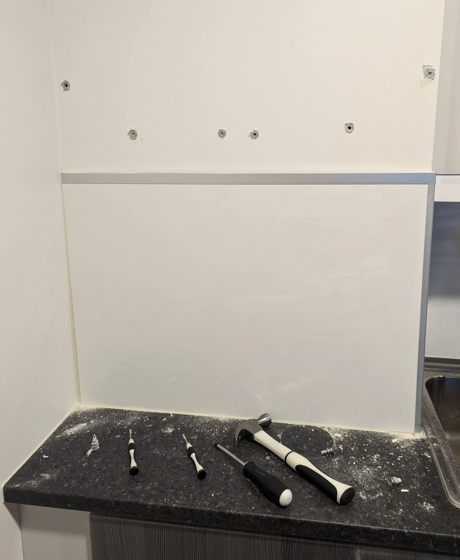
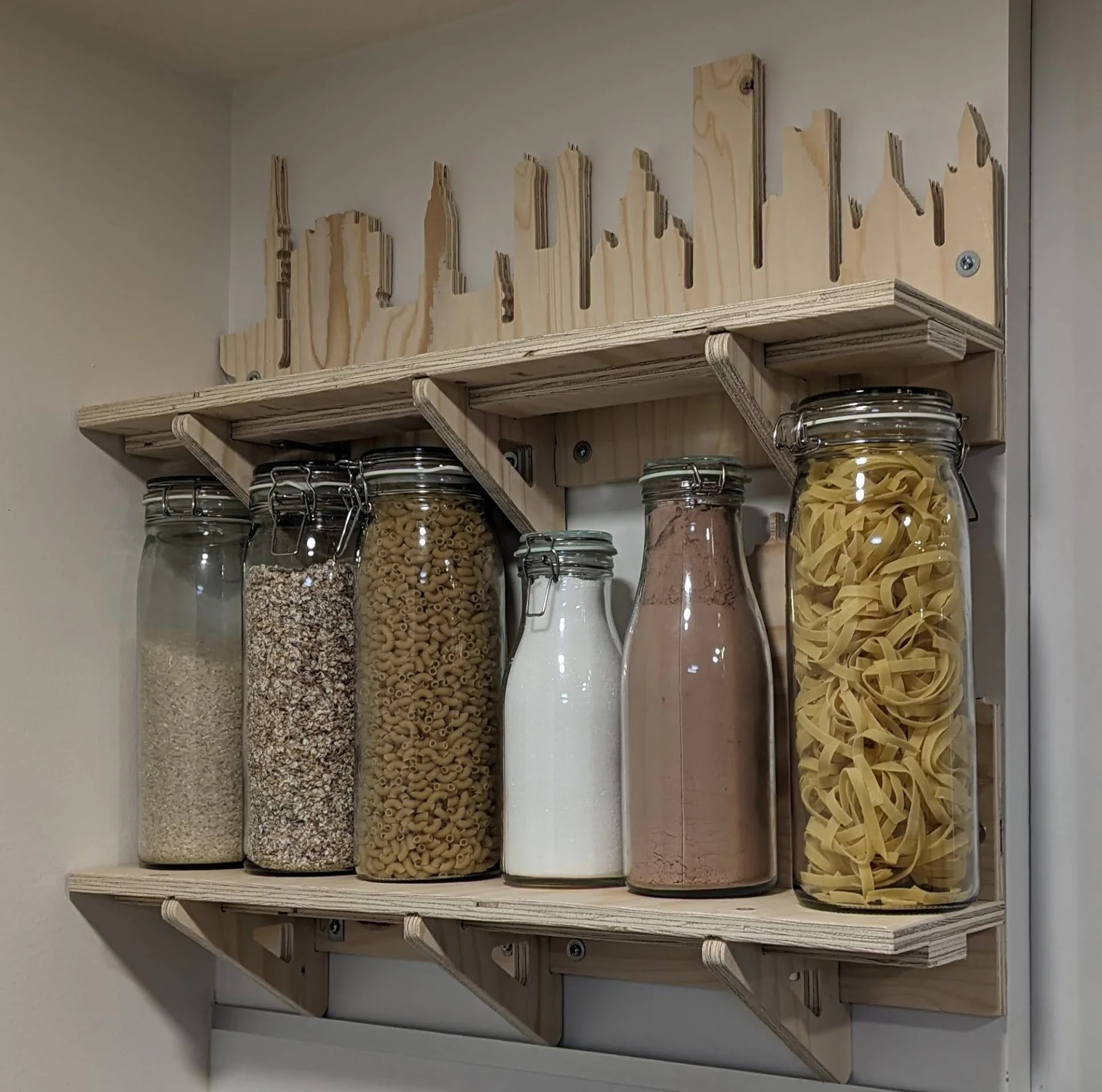
As the assignment was to make something big at approximately meter-scale as specified on the Fab Academy page, I had to immediately discard many ideas such as organizer boxes and a stand for our portable projector to mount it on the bedhead. I had to think bigger, which naturally led to seats, tables and bookcases but our apartment was already filled with those. Something which we had talked about for a while now, however, was to get shelves for a corner of our kitchen - shown below - where we could put jars of dried goods in order to gain more storage space and add a bit of color.
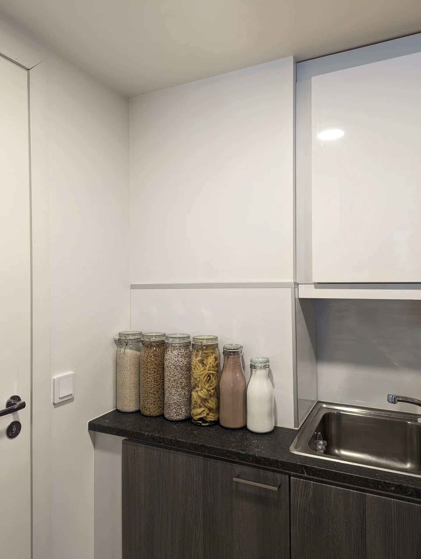
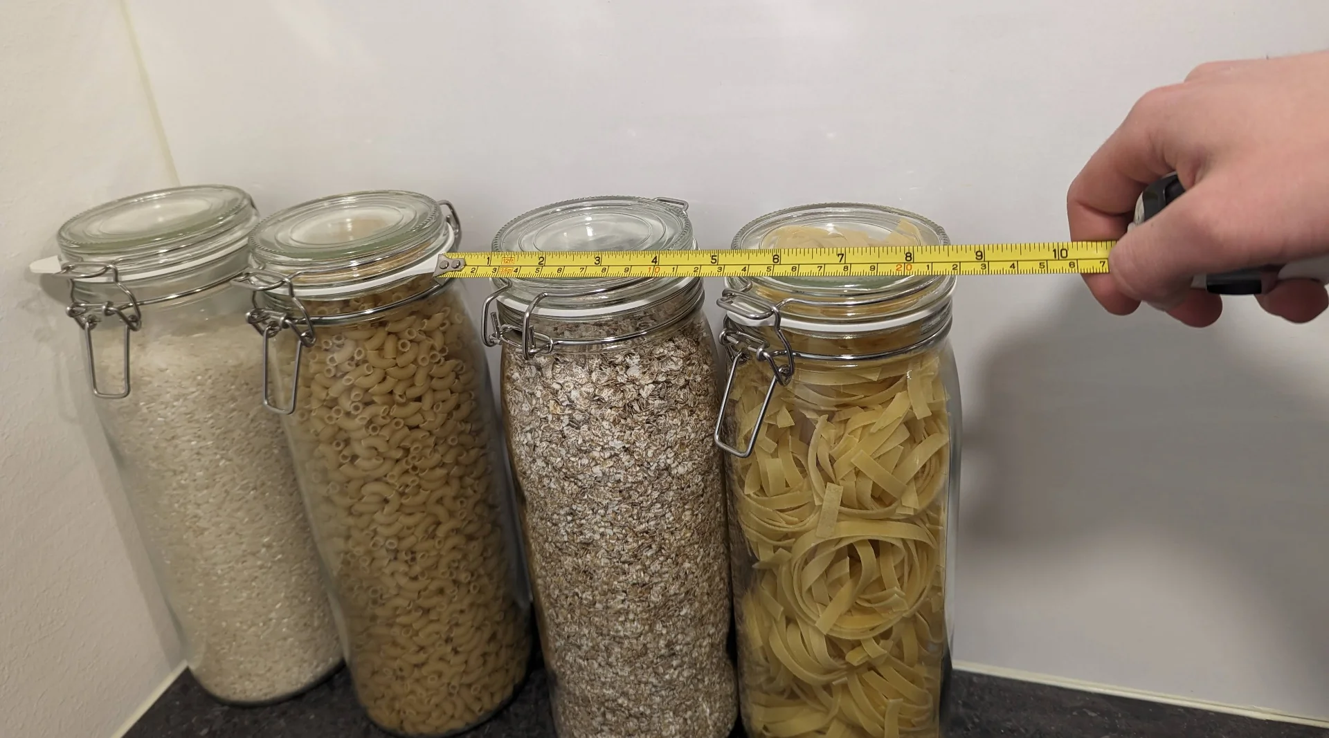
The jars were placed on the counter for reference. The idea would be to have two shelves on top of each other so that the lower one fits the larger jars (height: ~31cm, diameter: ~9.2-11cm) on the left and the upper one would fit the smaller jars (height: ~24-28cm, diameter: ~6.5-10.5cm) on the right. The wall area is approximately 69.4cm wide and 78cm tall. Given a thickness of 15mm for the plywood, the height would theoretically not be an issue with a naive approach of simply summing up all heights. However, a shelf obviously needs some sort of a support structure that can either be internal, such as in the case of thicker floating shelves, or external, which is necessary for such thin material as this.
In fact, the carrying capacity was my priority concern as the full glass jars were rather heavy and the 15mm thickness did not feel like much. Given enough time I would definitely have conducted a stress test but I started designing over the weekend and there were various difficulties (to be discussed furhter below) due to which I only finished my design by Tuesday morning, just before my machining time slot. My design was thus informed to a great extent by tryinf to attain a level of foolproofness, which I had to balance with the limited space.
The most obvious way in which the conflict and tradeoff between robustness and height constraints manifested was trying to figure out the height of the supports. I wanted to use triangular ones due to their stability and superior load bearing capability and I wanted to make them as large as possible to reinforce this but was quickly confronted with the height limits. I cannot count how many times I walked back and forth between my desk and the kitchen corner to measure something but eventually I ended up deciding that the height of the supports should be prioritized and as the wall area could accomodate a maximum of six large jars next to each other, I measured the top diameters of the jars and ended up placing the supports very carefully exactly so that between the edges and three supports it would fit precisely 1-2-2-1 jars (where a number indicates the number of jars on a segment and “-” indivates a support). The support width would be the 15mm and this was more or less exactly how much space there would be between the tops of the side-by-side jars.
The limited space and (literally) heavy requirements did certainly provide its own design challenge but I wanted something to explore the capabilities and limits of the CNC machine as well. Below is a snapshot of the design process put on “paper”, which may look like a bunch of incoherent scribbles - because it is - but it has all the information necessary for me to remember all alternative models, ensure adherence to material bounds and to sufficiently visualize some alternatives to make a decision on which one to pursue more seriously.
After consulting with my partner to get her opinion on what she would be willing to look at in the kitchen for the rest of our stay in the apartment, we mutually decided to go with the city backdrop design. As for the cities themselves, we chose Tampere and Munich as we are both originally from the former and she has lived a year in the latter as well. I could have made something abstract too but for something that is already custom in the first place it makes more sense to go all the way. Thinking of another alternative, it would be pretty cool to make silhouttes of one’s favorite fictional cities too.
Vectors
I then proceeded to browse skyline silhouttes of both Tampere and Munich with searches like “Tampere/Munich skyline silhouette vector” and found the following this one for Tampere and this one for Munich. I also used this as another reference for Tampere.
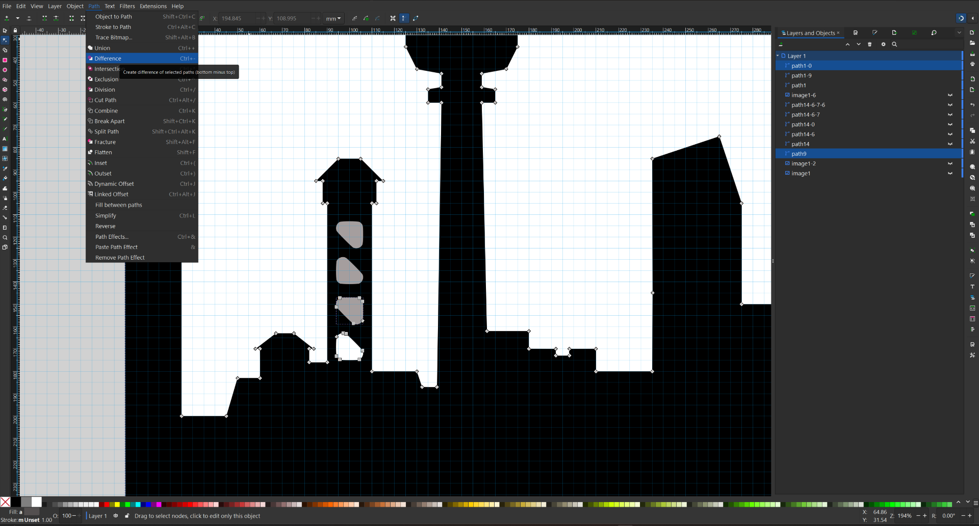
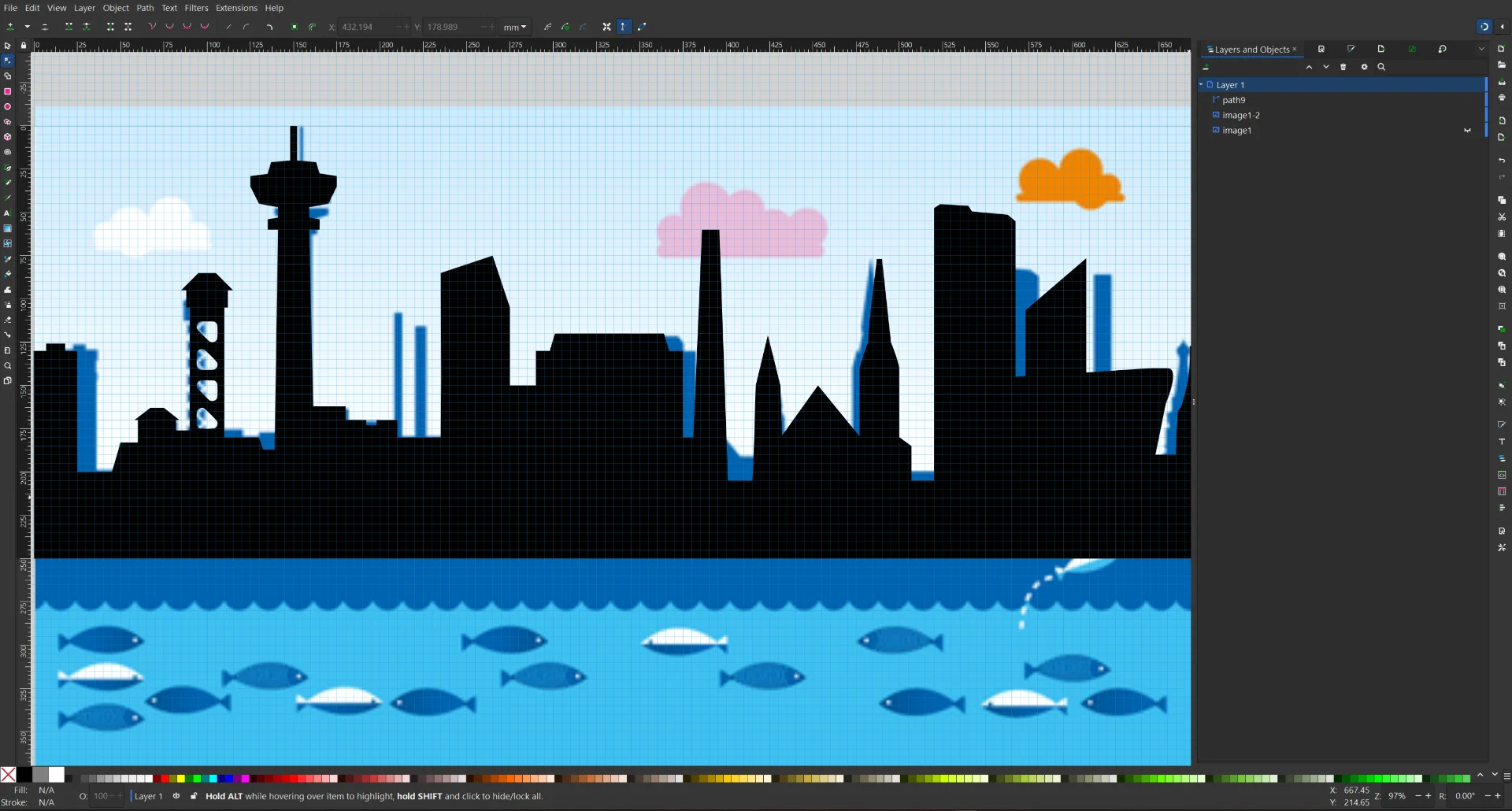
As the Tampere image was not a vector and it did not contain everything I wanted, I created my own silhouette based on it. I imported it to Inkscape, traced the outline using “Path” > “Trace Bitmap” with rather extreme settings (Threshold: 0.881 and Optimize: 5.000) and deleted the unwanted nodes such as the clouds and the fish. I then added a grid overlay with 1mm spacing in the “Document Properties” > “Grids” to aid with precision editing of individual nodes. With it enabled, I proceeded to fix the trace by making everything symmetrical that should be so and adjusting the spacing between the buildings. I also merged the different components of Näsinneula (the highest tower) by positioning them so that they overlap slightly and clicking “Path” > “Union”.
I then proceeded to remodel most of the buildings node by node with extra care put into the iconic, even emblematic Näsinneula, while removing many and drawing additional ones such as the Nokia Arena and Hotel Torni. I also overhauled the haulitorni entirely to be machinable with a 6mm milling bit. I made sure that all the spaces to be milled were at minimum 6mm thick and I made all relevant outer corners so that they could be milled sharply. The rest I was curious to observe and willing to accept however they would turn out. For the haulitorni this meant small rounded triangles cut out using “Path” > “Difference” to symbolize the staircase lattice framework. To make absolutely sure I had the dimensions right, I drew it as a triangle with stroke width of 6mm and then traced it into a new filled vector.
The final result with dimensions of 690mm x 250mm (reduced for the webpage) can be seen below.
I did the same for Munich but with much smaller modifications, only making sure that it was well machinable, as the reference image I found from Google Images on a site called “Free Vector Art & Graphics” was, in my opinion, better already and I was not as familiar with Munich in general despite my brief visit last summer when we had to purchase an additional suitcase to carry back all the books we bought.

Below is the resulting, refined 690mm x 230mm (reduced for the webpage) vector.
3D modeling
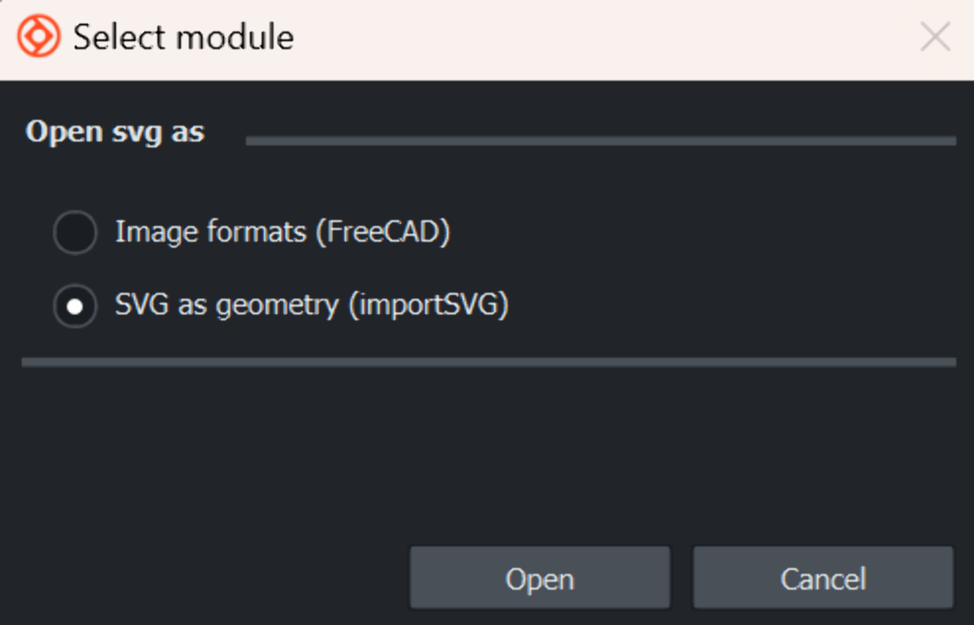
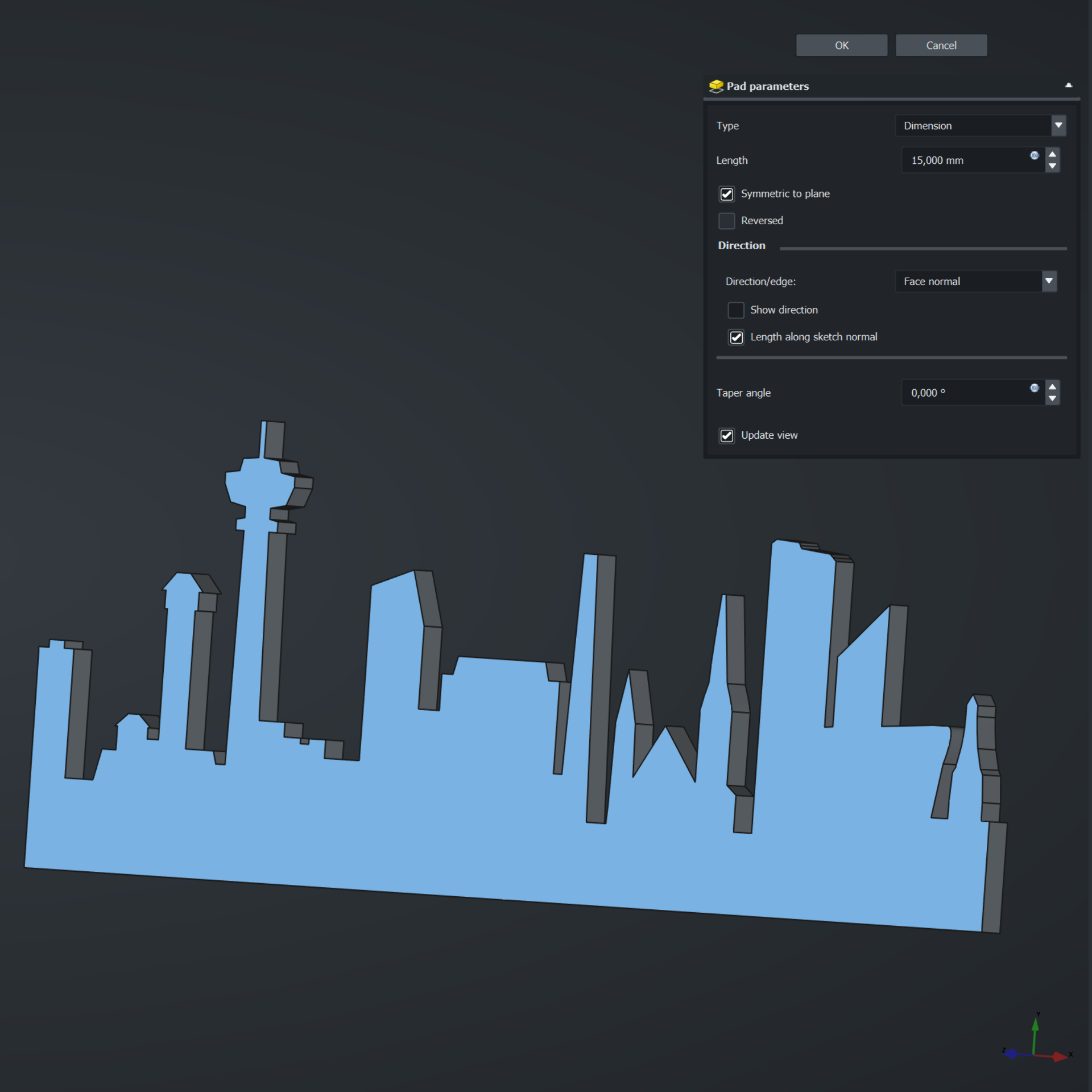
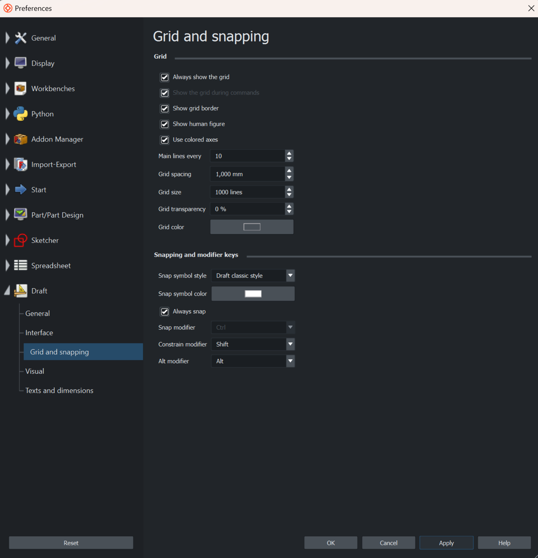
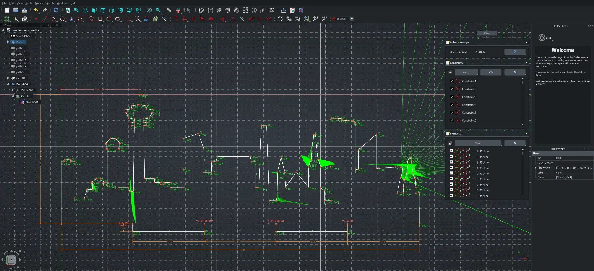
I then attempted to use Ondsel for designing the actual shelf by importing the SVG, extruding it and adding joints to it. The importing was pleasantly straightforward with correct scaling as well but I found it rather peculiar that the SVG was not similarly straight across the “Part Design” and " Draft" workbenches. I wet to adjust the grid size in order to envelope the entire shape and tried to troubleshoot it but later I realized that the bottom and side nodes had not perfectly snapped to the grid in Inkscape. I had practically fully designed the first verion of the shelf when Ondsel betrayed me and all 18 backups of the project that I had spent the entirety of Sunday exploratorily making were corrupted. I suspect this might have something to do with the fact that I edited the city vector as a sketch and forgot to use the lock constraint on the non-adjusting parts but that should still not happen. I lost practically all my work and so Ondsel/FreeCAD lost me as a user, at least for the rest of the course and complex projects.
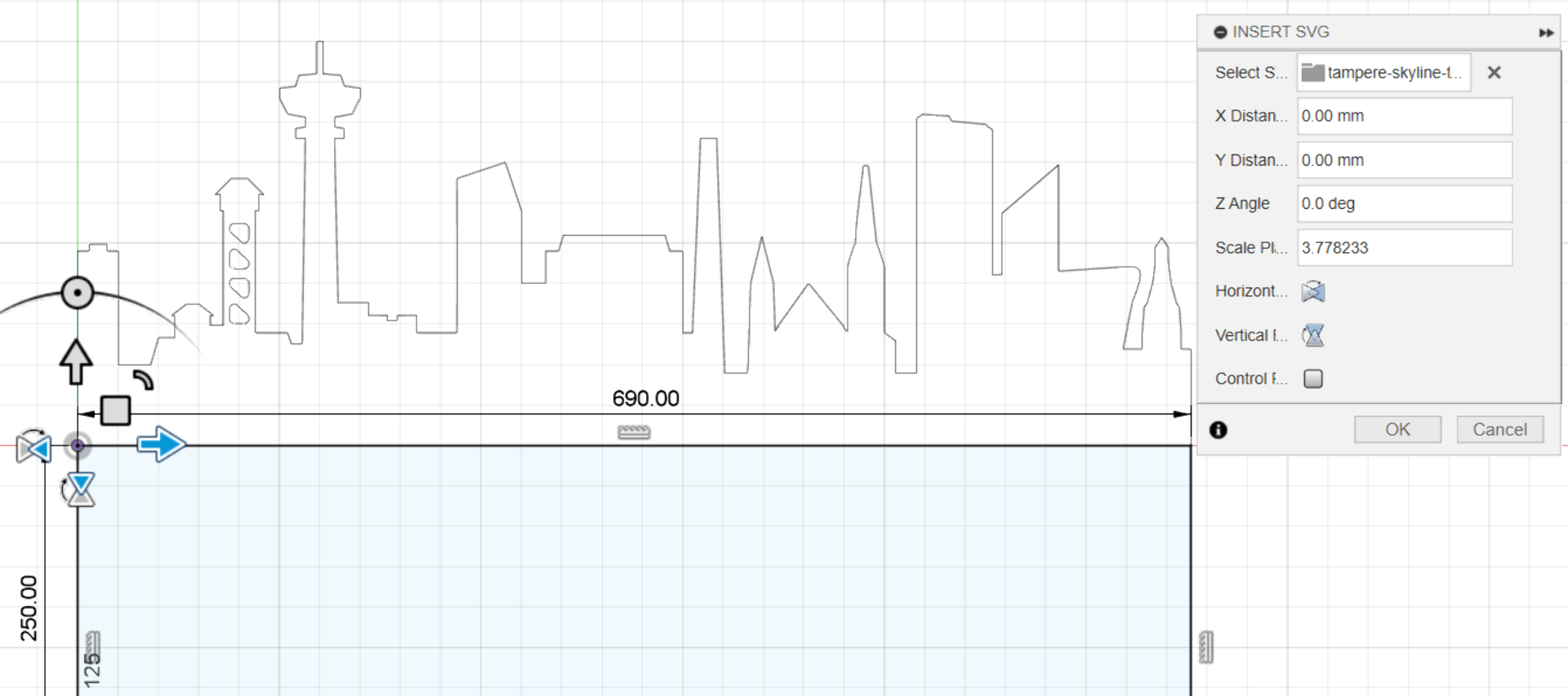
I decided to then start over in Fusion 360, with which I was more comfortable already anyway and which I knew to be significantly more stable and reliable. It did have a weird quirk though, of which Ondsel did not suffer: the vector was not correctly scaled upon importing the SVG file via “Insert” > “Insert SVG”. I had to scale it by an arbitrary factor to match the original width, which was exactly 3.778233 for Tampere and 3.7795275 for Munich, even though they were the same width (different heights by 2cm difference though). The way by which I found the factor was to define a width parameter in “Modify” > “Change Parameters” and assign it to the horizontal edge of a rectangle and then trying out different scaling factors by increasing any decimal part until the vector width exceeded the rectangle, backtracking by one and adding a new number until I ran out of zoom to determine any substantial difference.
The shelf design using the below parameters is relatively simple. It contains the city background board, which was created in Inkscape, imported to Fusion 360 and scaled and then added to with the regular sketching tools such as lines and rectangles, the shelf component itself and triangular supports as well as a long rectangular one. The values below are relatively straightforward with thickness referring to the plywood material’s thickness, depth to how far the shelf reaches from the wall, height to the size of the triangle supports as opposed to the entire thing, load_diameter to the top diameter of the jars to be placed on the shelf and snugness to how much room would be cut for joints.
| Name | Value |
|---|---|
| thickness | 15mm |
| Width | 690mm |
| dedpth | 160mm |
| height | 110mm |
| load_diameter | 106mm |
| snuggness | 0.1mm |
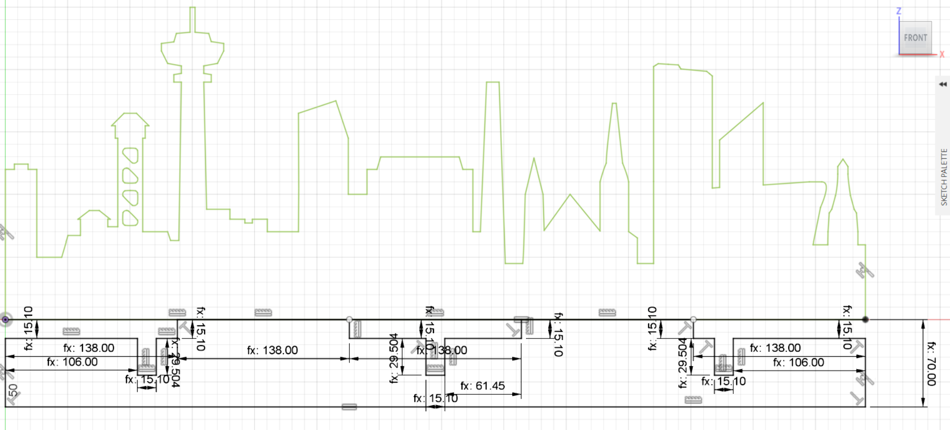
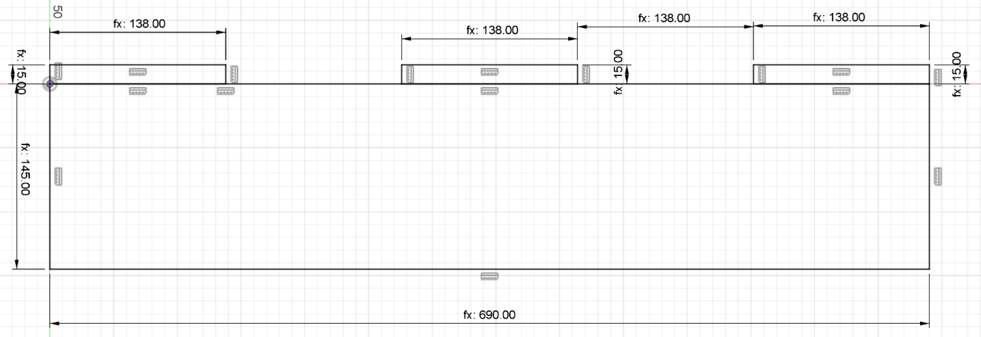
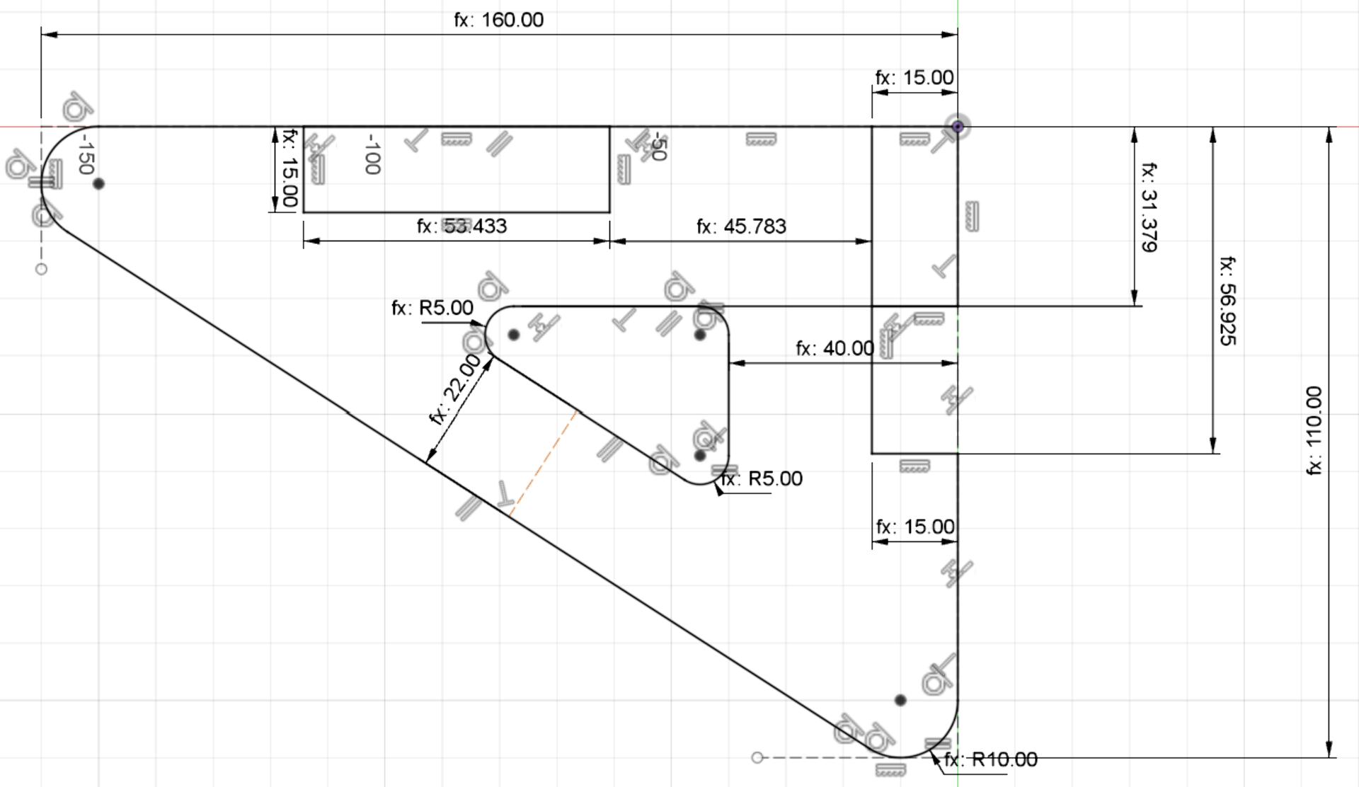
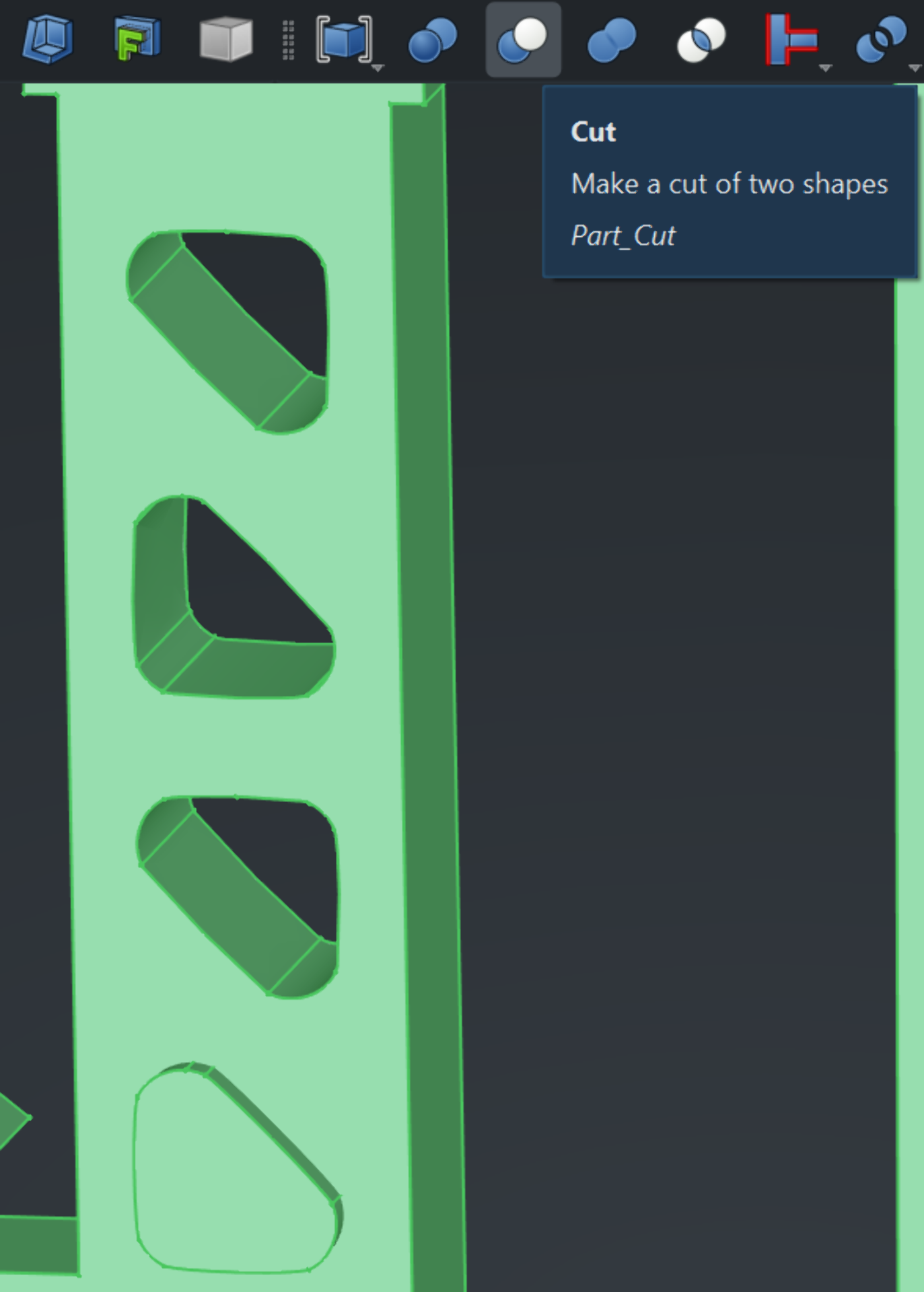
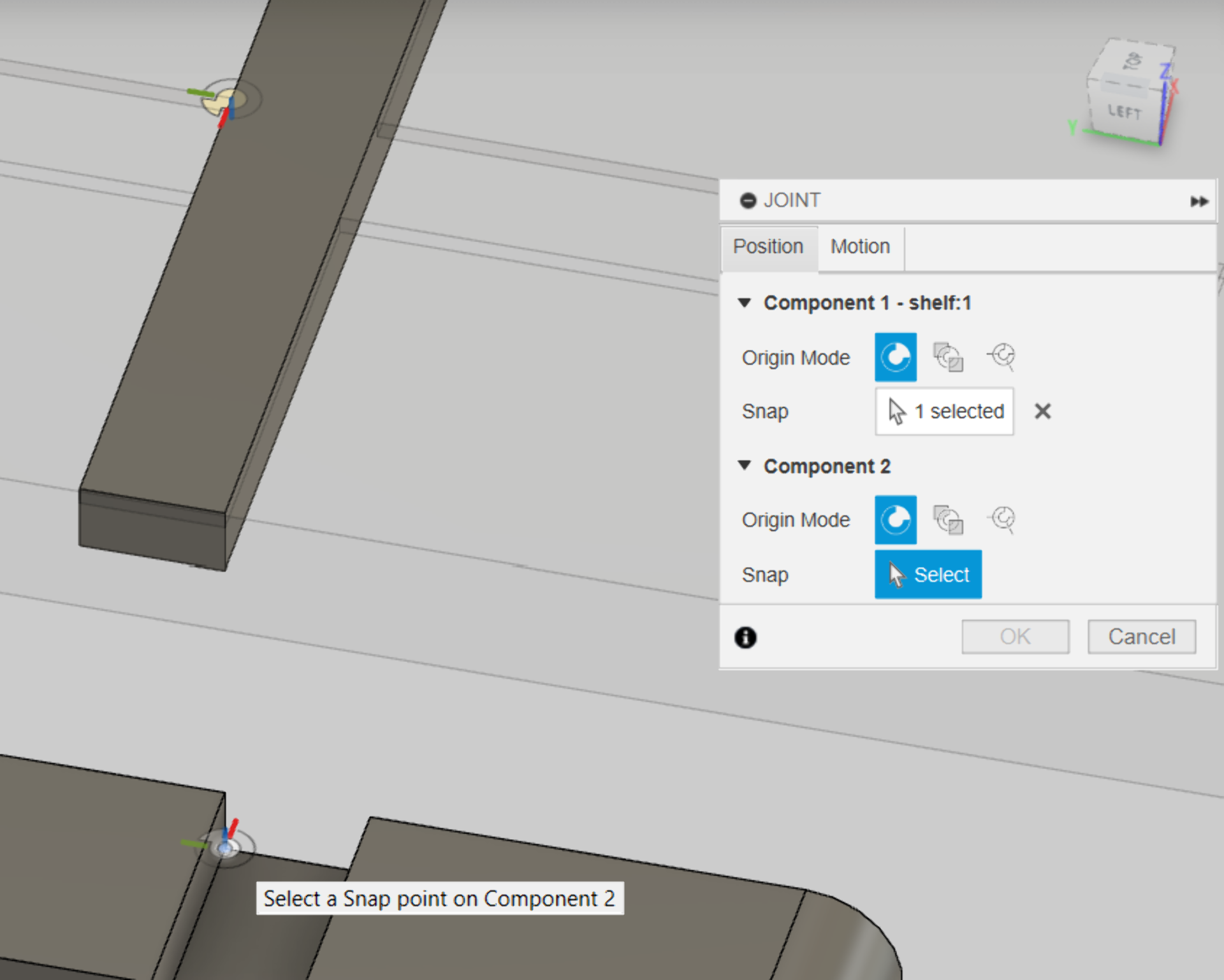
The green highlight of the city signifies that the city is fully but non-parametrically constrained (meaning it cannot be adjusted with the below values). The black part, however, signifies a regular fully constrained sketch that is attached to it. The idea for the three T-slits is to accomodate the joints connecting the shelf and supports to the back board. Why the board stretches beyond them is for easy installation to the wall, where it should be sufficient to drill screws through the extension part, hiding most of them from direct line of sight when viewed from above and making the installation process easier. The shelf connects to the background via three joints and the triangle connects to both the background as well as to the support bar, which rests on them.
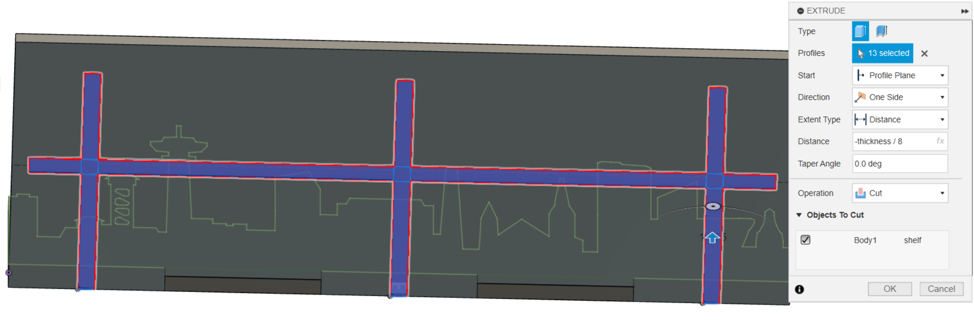
To align the components properly in the assembly phase as well as to make them fit tighter, I added a pocket for the supports by creating a new sketch, which I extruded into the shelf by approximately 2mm (thickness / 8). The final support bar is significanttly wider than that depicted in the screenshot below.
I then assembled the parts into the first shelf, duplicated it, replaced the Tampere background with Munich and proceeded onto experimenting with the measure tool to make sure they would fit properly and leave enough space for the jars in all directions.
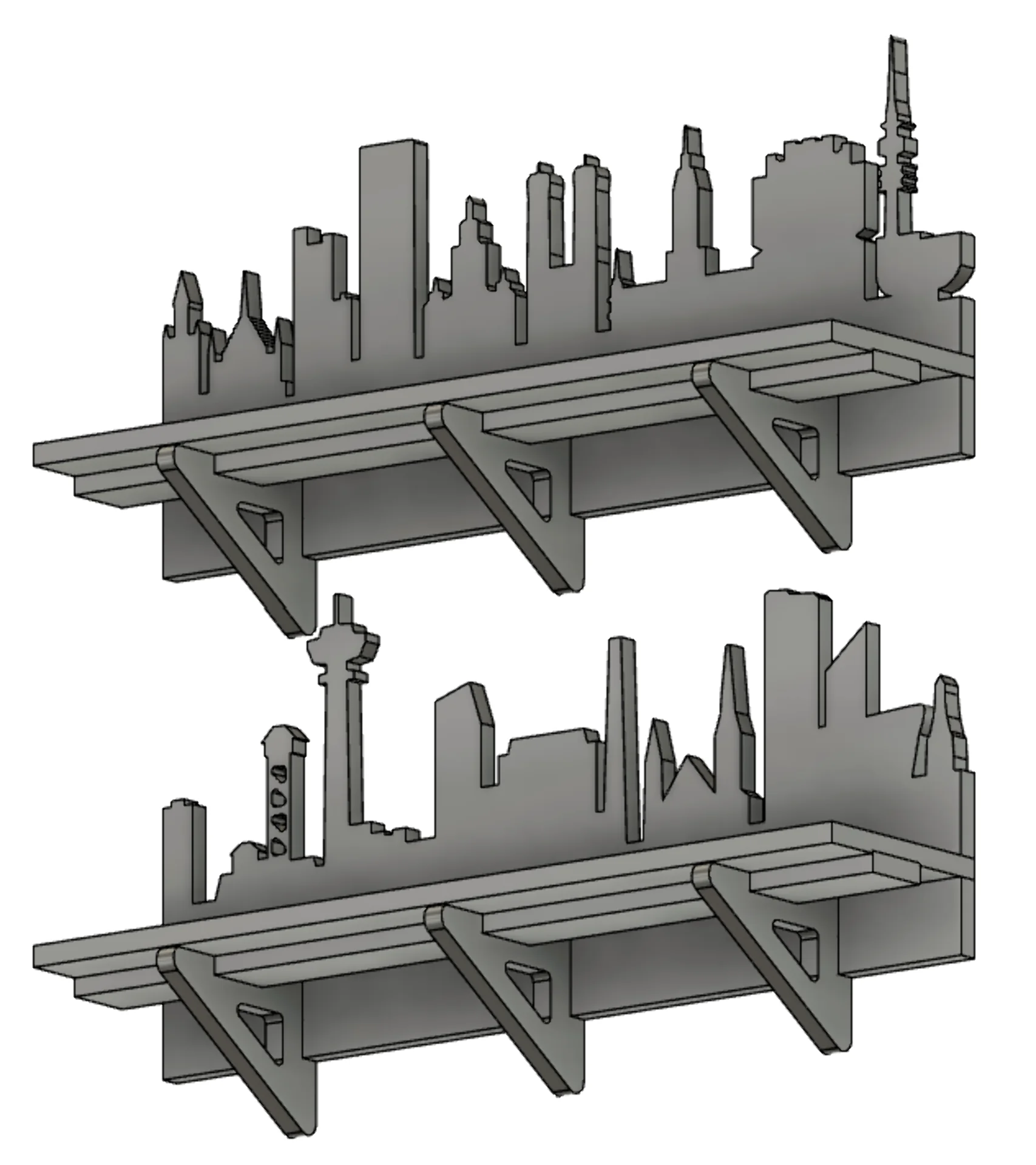
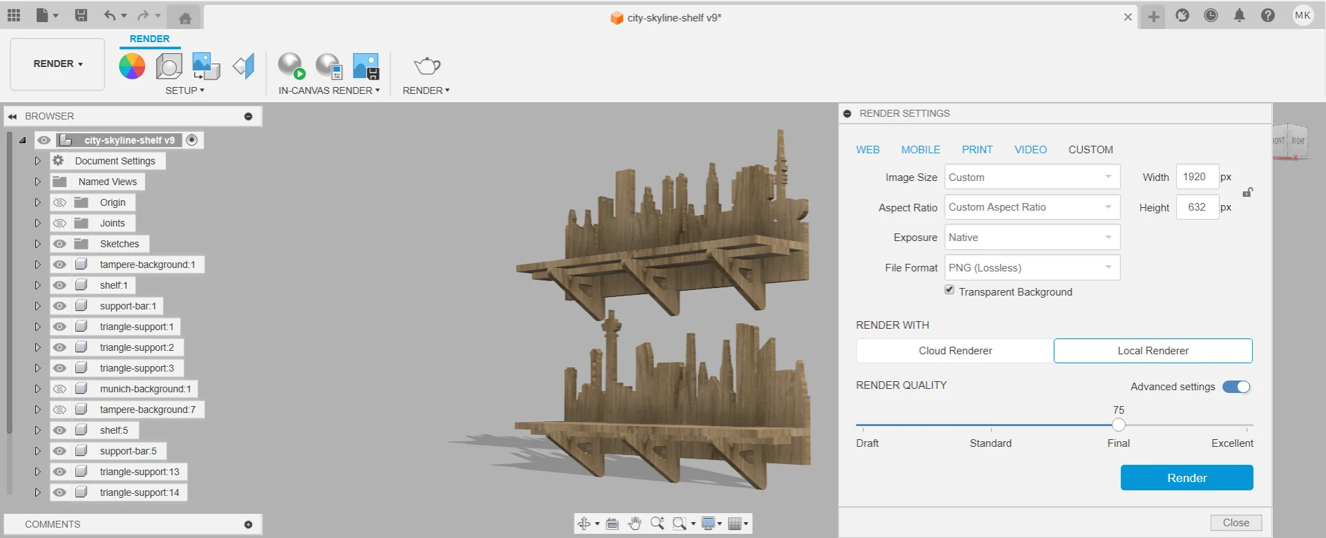
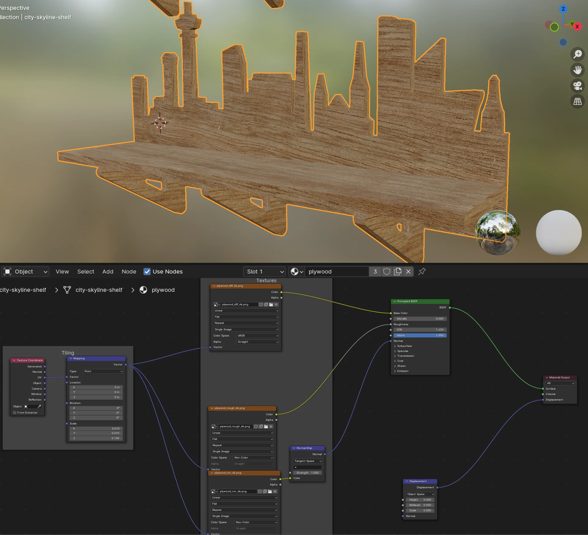
Out of curiosity, I also tested the Fusion 360 render workbench, which was very streamlined and straightforward so that creating a render was very quick and easy but there are not many options for adjusting it. I chose “Oak” as the material from “Appearance” > “Library” > “Wood” and applied it to all the bodies. I then locally rendered the image below with “Render Quality” of 75 and dimensions of 4000px x 4000px as for some reason it added a lot of white space around it. Cropping the image to around 1200px x 1200px then produced the below image.
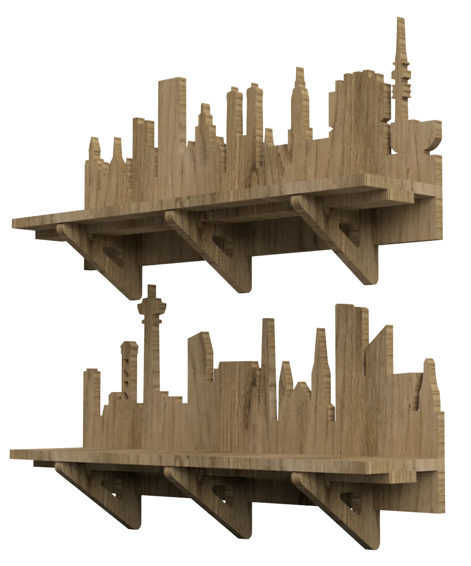
I wanted to again display it as a 3D model using modelviewer as well but no .glb export option was available and when exporting as .obj from Fusion 360, the texture was not included. I thus searched for a plywood texture on the internet and found one here. I opened the example project that came with it and replaced the sphere in it with the .obj of the shelves using X- and Y-scaling of 0.01 for the texture in the shading view. I then exported it as .glb and displayed it below using my custom 3DModel Hugo shortcode.
CNC Milling
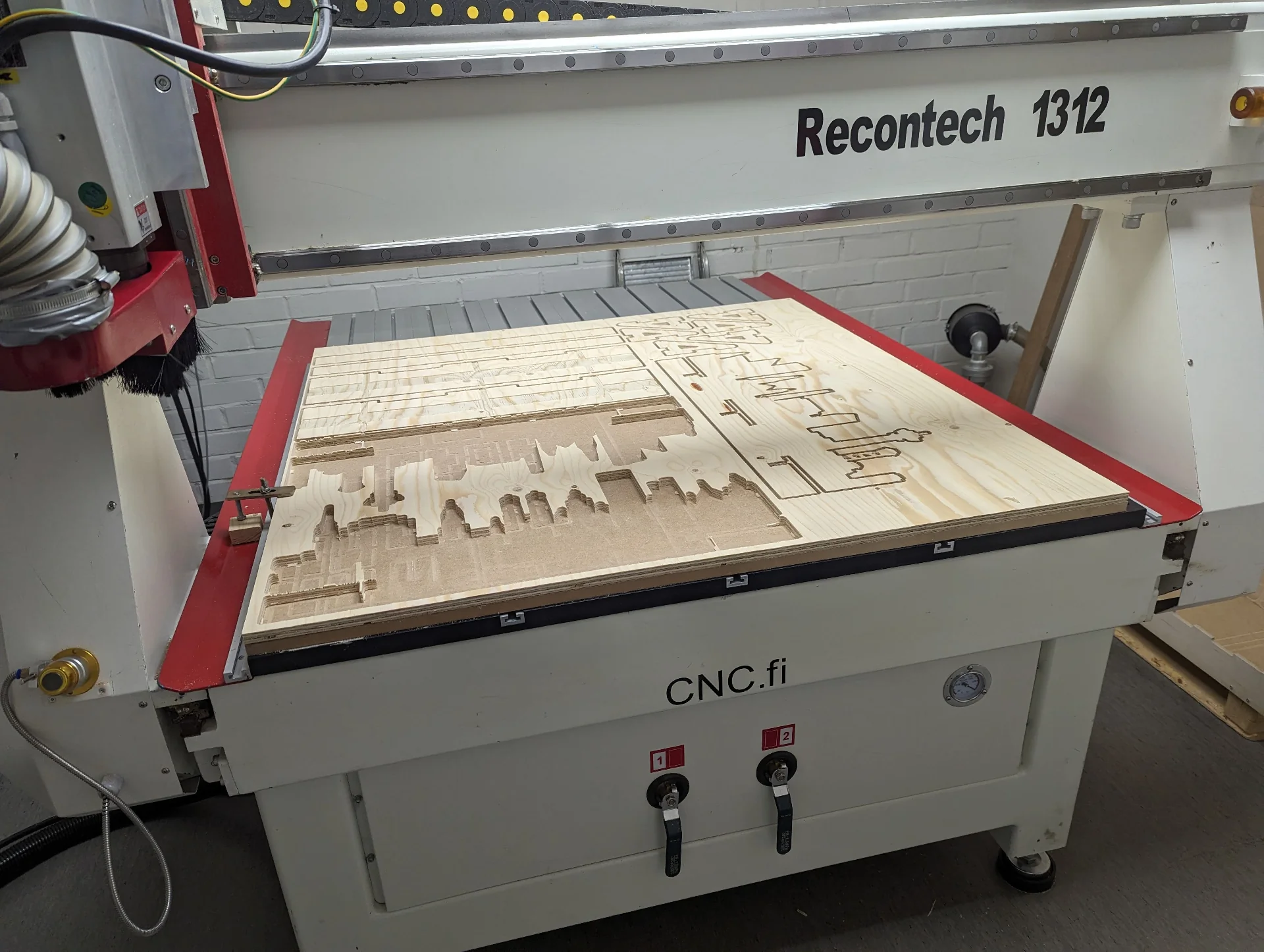
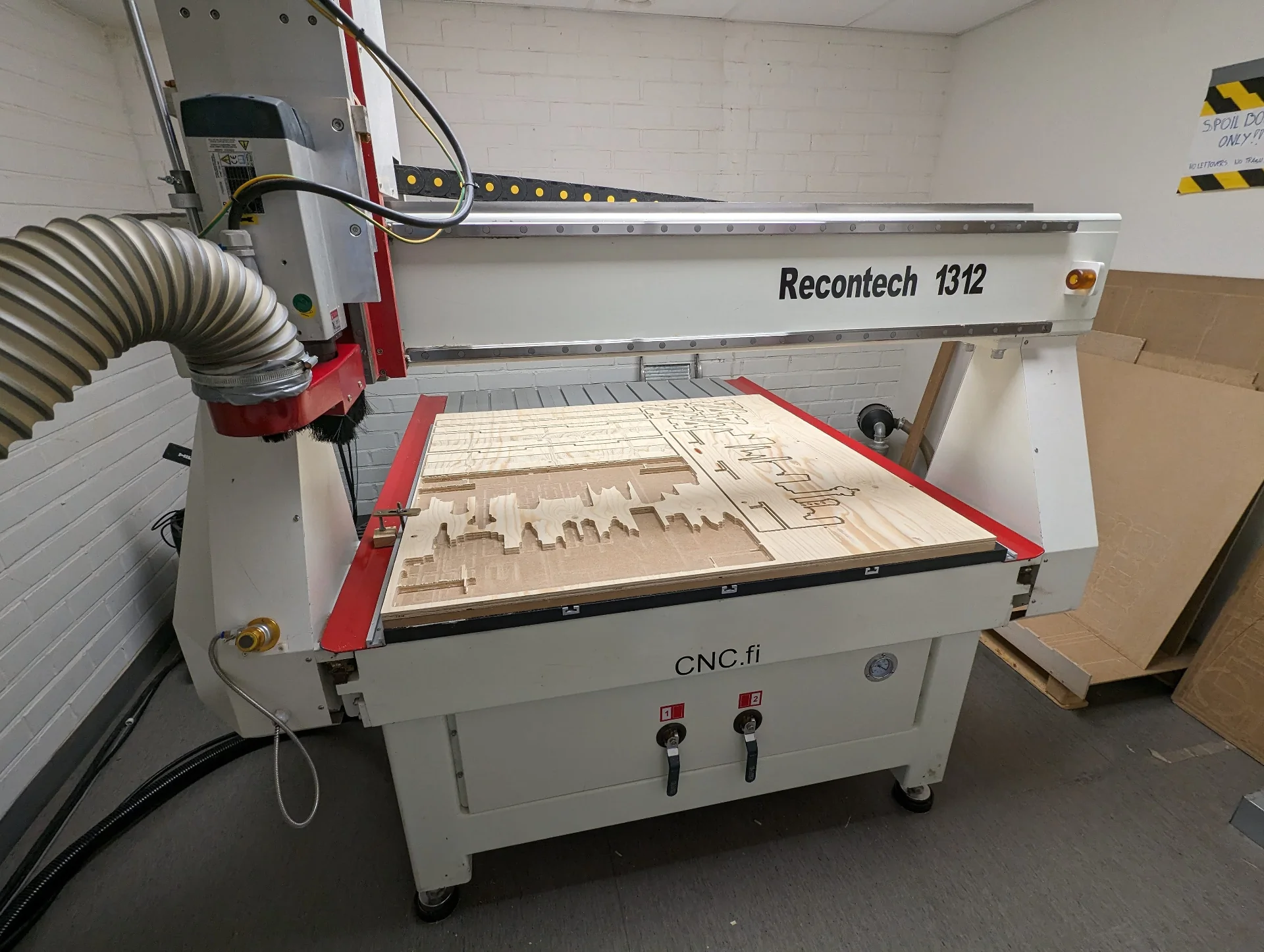
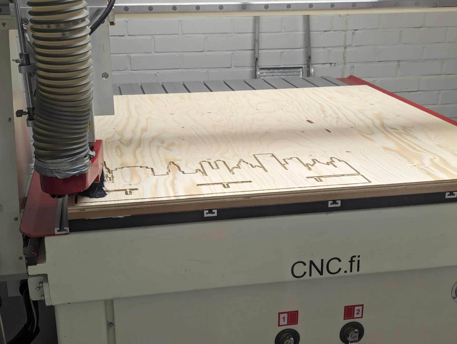
Our lab had the Recontech 1312 CNC machine, which I used to mill the parts. We each had 2-hour slots for machining, which barely got me started - likely because I was the very first one who had booked a slot and the process might not have been established and streamlined properly yet. Additionally, we managed to bump into many software issues that even the instructors had not previously encountered. I will document my particular process below but once more Aalto FabLab Wiki has great documentation for 2D milling with recontech 1312 in addition to which there is an 80-minute video for an even more exhaustive overview of the entire process here.
Safety
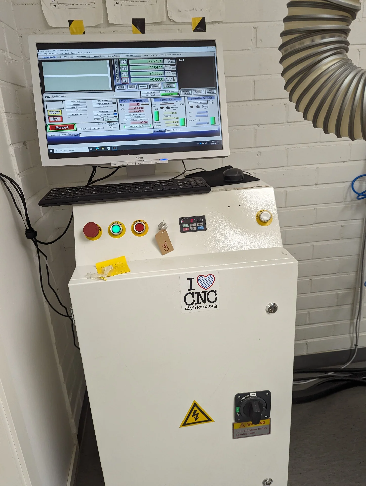
Use of gloves is recommended with materials that might splinter but explicitly not when using the machine, as they might get tangled up and pulled in. The large, red emergency stop can be found in the control box in the top left corner of the control unit below. The vacuum bed is very loud and thus ear protection is also highly recommended. Additionally, there is a first aid kit in the workshop in the lower, grey cabinet with sliding doors next to the blue cabinet by the second entrance if needed. Make sure to have long hair tied up and avoid loose clothing and only run the machine from outside of the room but monitor it through the window in the door. Calculating an appropriate feed rate and being aware of the cut area if using clamps is also crucial.
Creating toolpaths
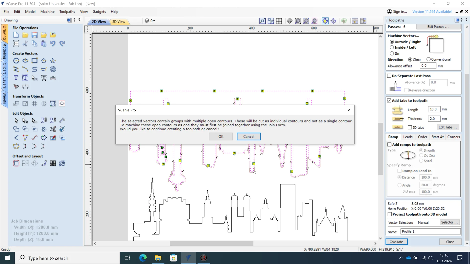
I exported the sketches in .dxf format by individually selecting them from the tree view in Fusion 360 one by one and choosing “Save As DXF” from the context menu brought up by a right-click, which, however, is not necessarily the smartest way as discussed in the reflections at the bottom of the page. Those can be found in the repository here. I then uploaded them onto a USB stick and carried that over to the computer used with the machine. I imported the .dxf files into VCarve Pro and discovered some difficulties with that. The exported .dxf files included the sketch guidelines in addition to which they had accumulated some duplicate lines other than those too. This then resulted in various different types of unintended behavior such as a warning in creating the toolpaths in the milder end and setting the toolpaths on the inside even when outside was selected in the more baffling, annoying end.
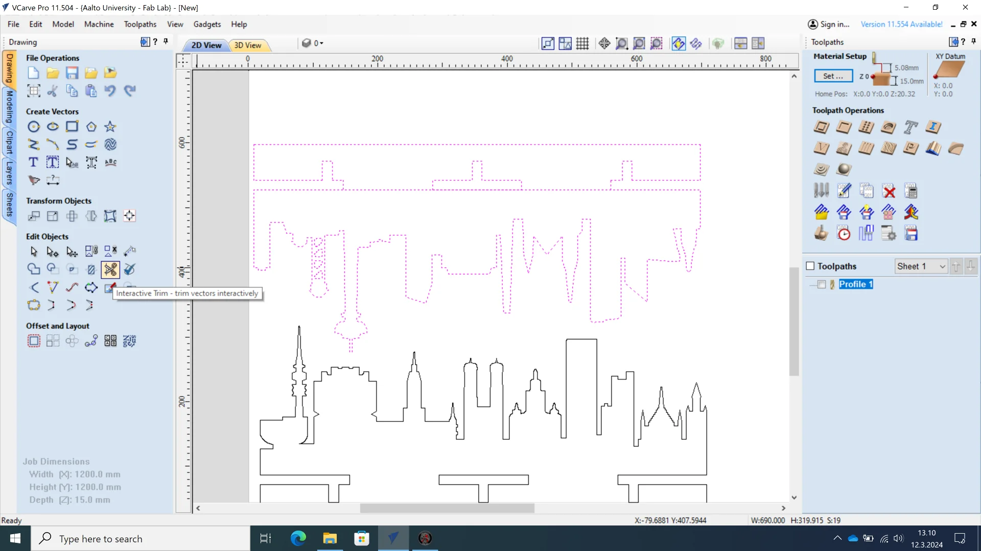
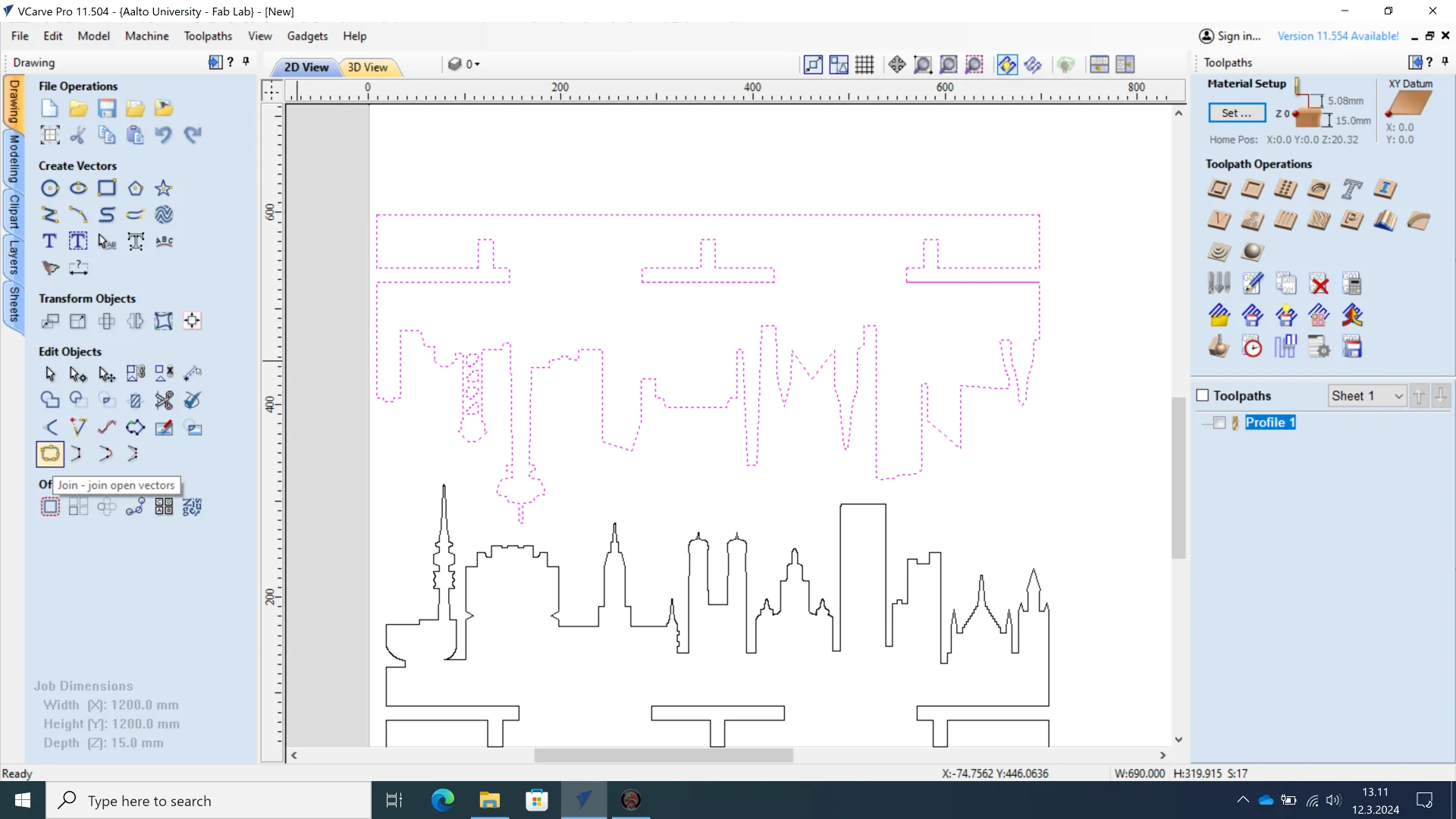
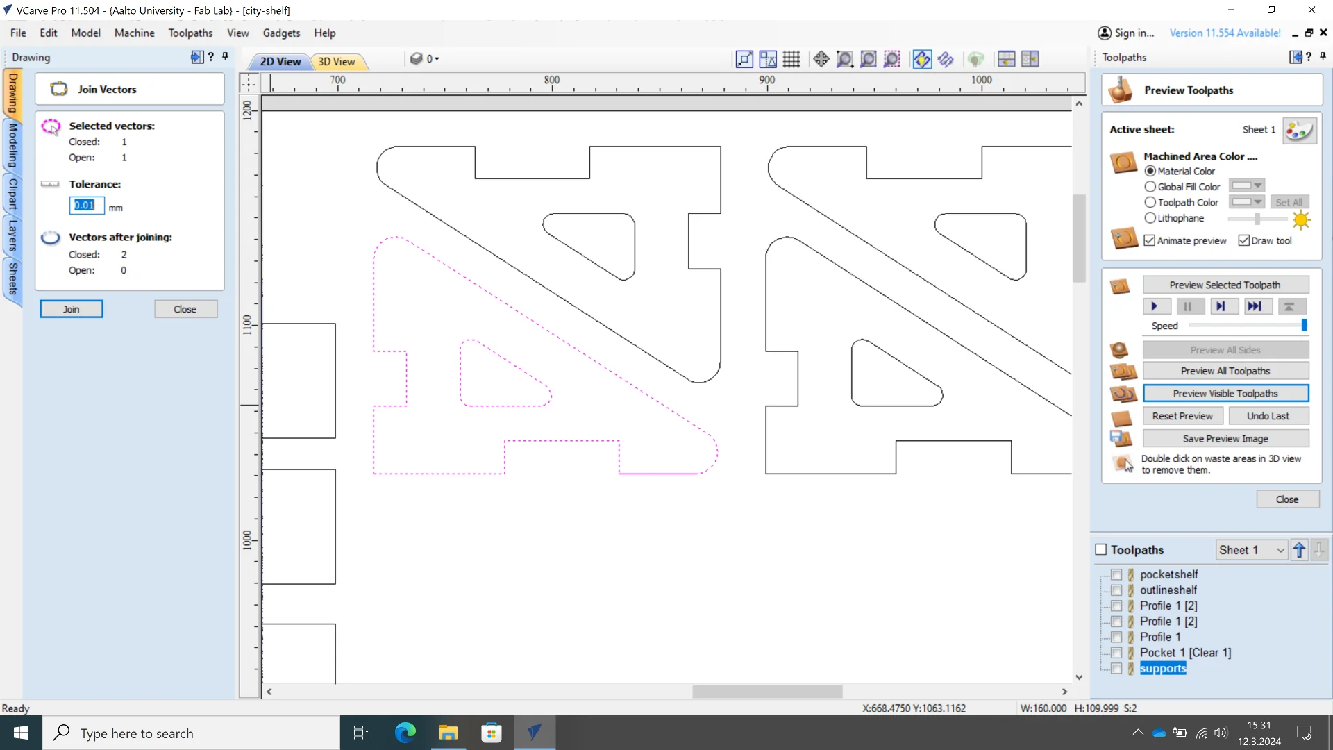
This could be solved by using the “Interactive Trim” tool to cut out the undesirable guidelines as well as the intersecting and overlapping lines. In theory this is as simple as just clicking on the lines to be deleted and merged but in reality it sometimes felt like the computer bits had to be flipped just right by sunrays penetrating and hitting them at a particular angle because of how fiddly deleting particularly the overlapping lines was. I did manage eventually, after which I could then join the vectors using “Join” once all overlapping lines were certainly deleted. One way to detect them was to ungroup the vectors and then just select each of the faces if the entire thing did not get highlighted when doing so. A successful join operation can be inferred from the number of open vectors being 0 after the operation.
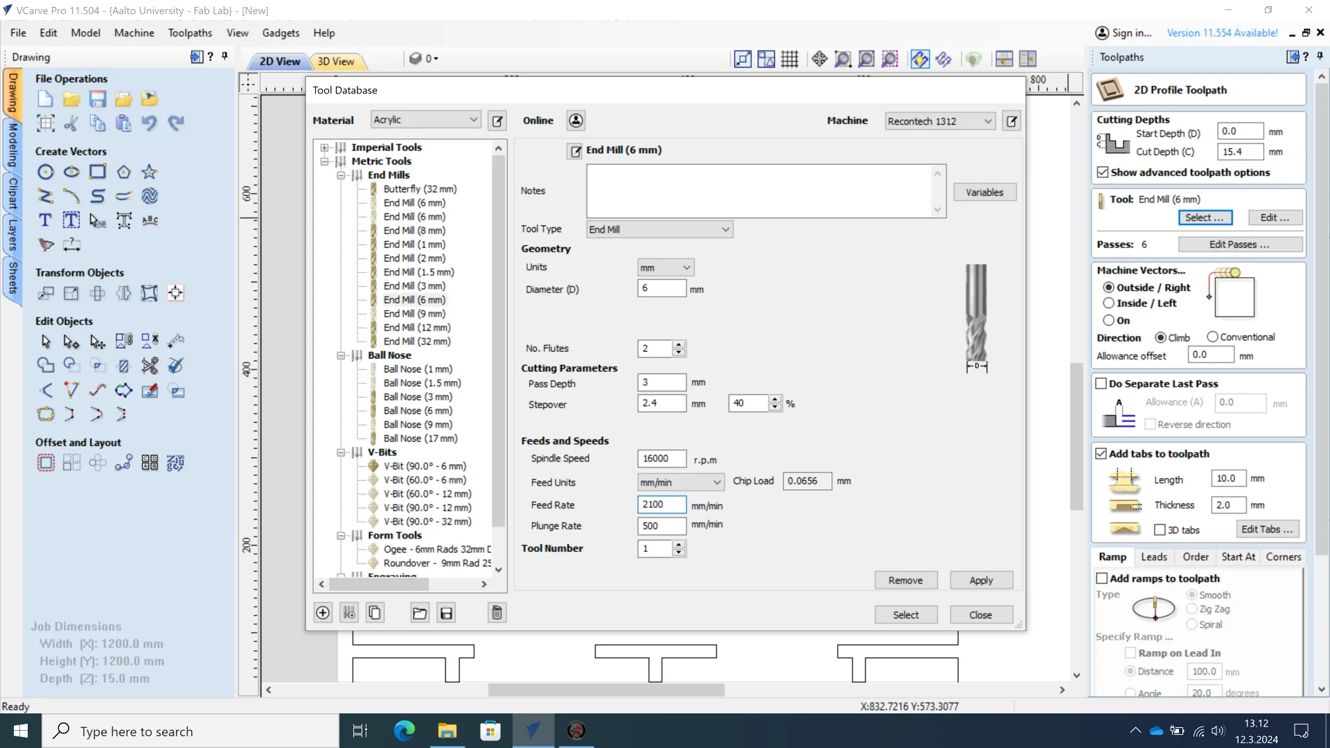
I created a “2D Profile Toolpath”, set the cut depth to 15.4mm, which was recommended to us by our instructor, given that we had a sacrificial layer beneath the material, and input the below tool settings:
- Diameter: 6mm
- No. Fluters: 2
- Pass Depth: 3 mm
- Stepover: 2.4 mm 40%
- Spindle Speed: 16000 r.p.m
- Feed Rate: 2100 mm/min
- Plunge Rate: 500 mm/min
Most of settings were set correctly by default and only needed verifying, which could be done by referring to the Aalto FabLab wiki entry on 2D milling with recontech 1312. Due to the limited time slot, the milling bit was pre-installed for us but it can be changed by moving the vacuum tube to the side and changing both the collet and the bit as shown here. The particular tool we were using had 2 flutes (the cutting edges) and a diameter of 6 mm. We were told that the optimal pass depth would be equal to the radius of the tool and a stepover of 2.4 mm made it fast to move the tool around when not milling with enough of a margin of safety. The Recontech 1312 is rated for a spindle speed of upto 20 000 revolutions per minute but we were instructed to use 16 000 r.p.m with a plunge rate of 500 mm/min for safety. The feed rate could be calculated using the following formula:
Feedrate (mm/sec) = Number of Flutes X Tooth feed (mm) X RPM (mm/s)
Tooth feed for the above equation is dependent on the cutter diameter and the type of material to be milled. A lookup table can be found here, which gives a value of 0.060 for 6 mm and soft wood. This results in 1920, which we initially rounded down to 1900. After my time was starting to run out, Solomon Embafrash, Aalto FabLab’s manager told me it was fine to increase it to 2100 mm/min due to how soft the plywood was and most of my parts were milled with that setting with a decent outcome.
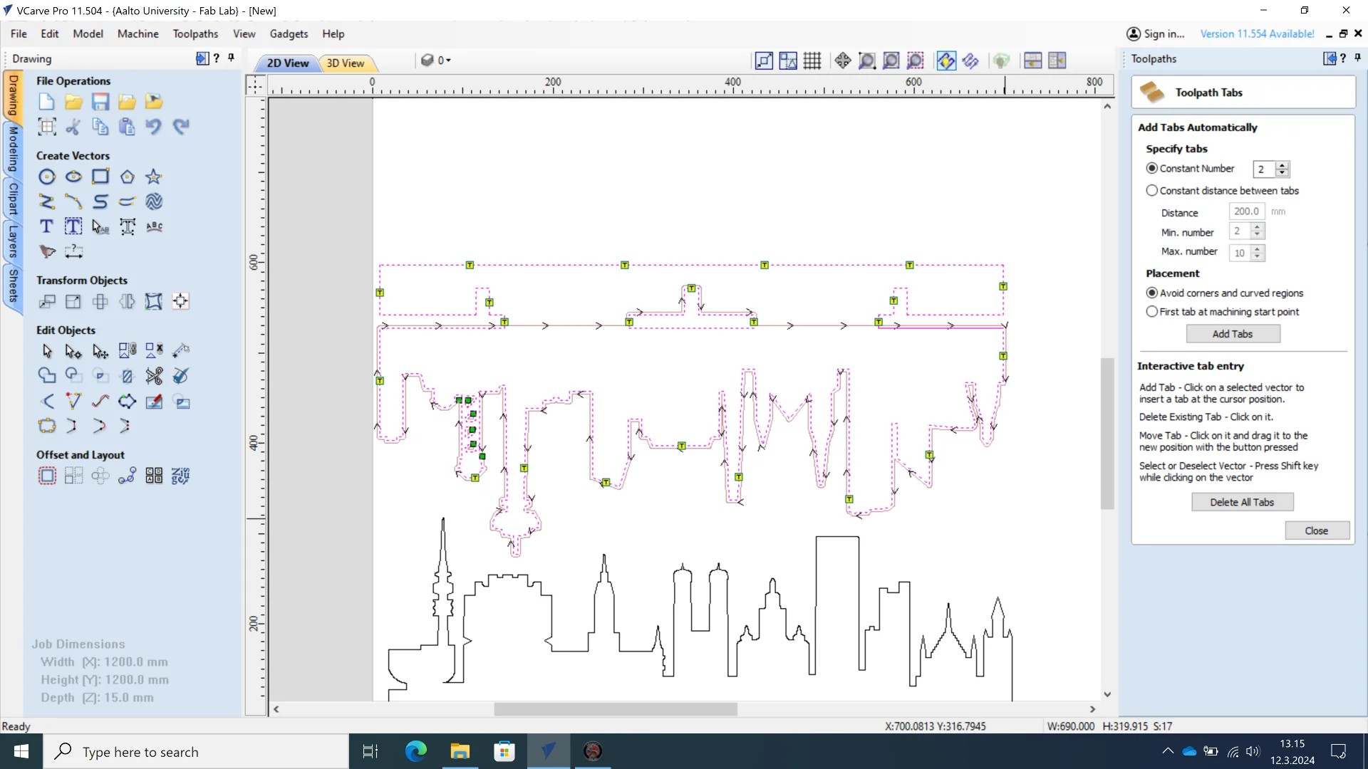
I then added 10 mm wide and 2 mm thick tabs to the nearest straight paths at regular intervals and close to critical points to keep the milled part in contact with the rest of the sheet to avoid vibration, which might cause splintering and non-optimal cutting.
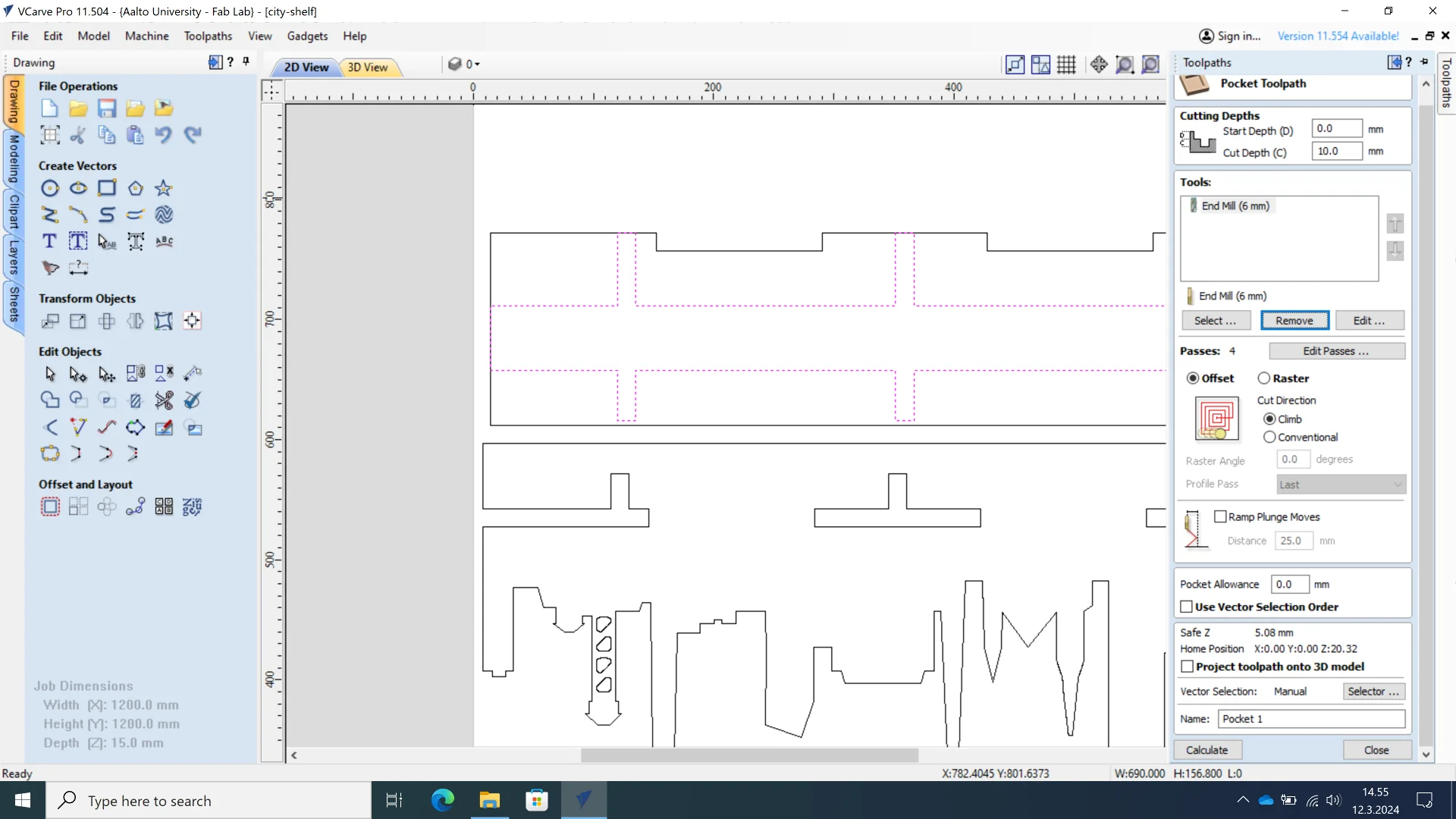
I then added a pocket 1.875mm (thickness / 8) deep to correctly align the components under the shelf using the “Pocket Toolpath”.
I had forgotten to add “Dog-Bone” fillets for the first test city background slits to compensate for the mill bit’s roundness when trying to fit the components together. Having realized this, I did remember to add them to the rest of the parts by navigating to “Fillet”, choosing “‘Dog-Bone’ Fillet” and clicking the corners I wanted one to be added for. Removing them was also simple by clicking the arcs if one were misplaced.
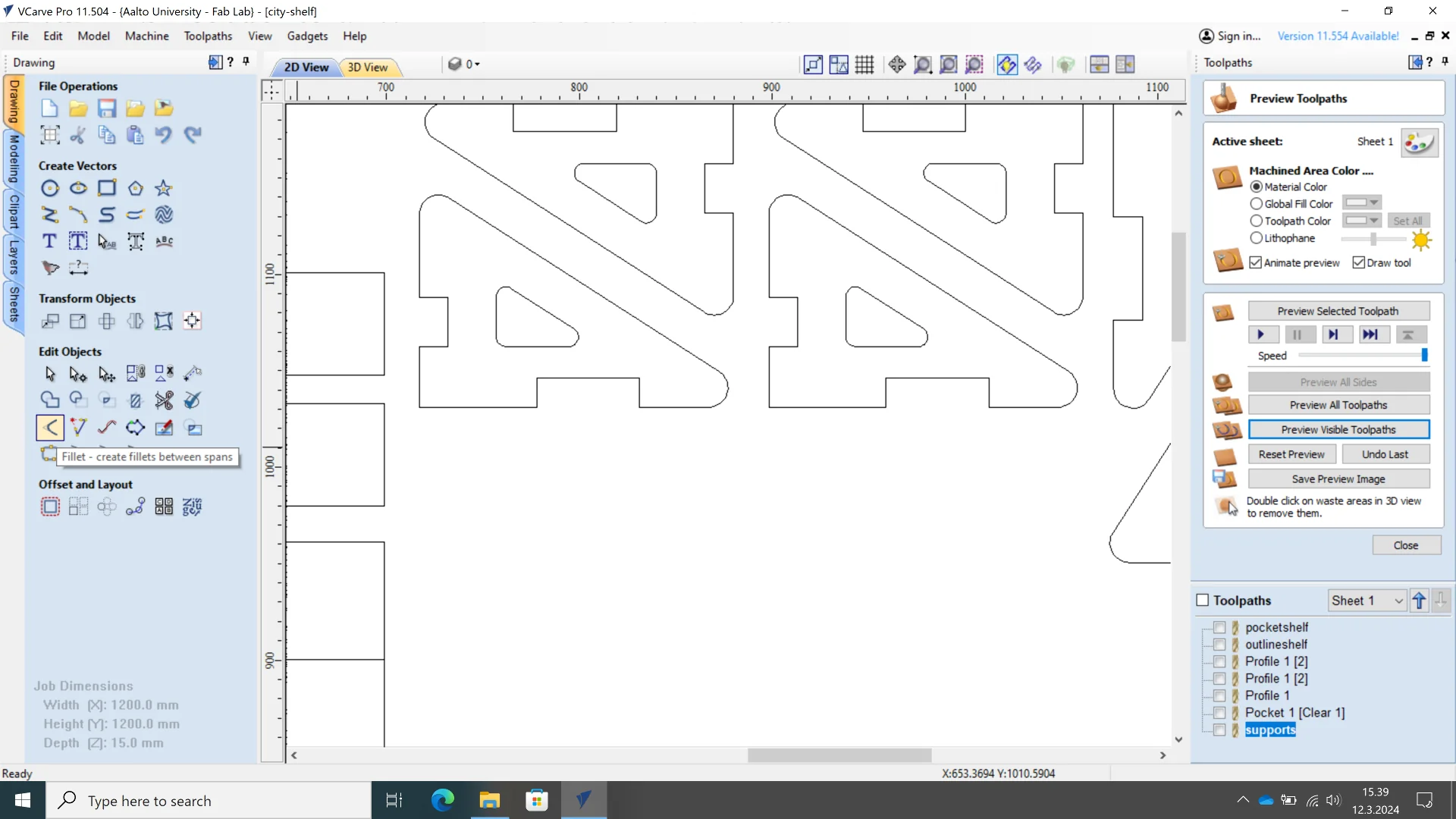
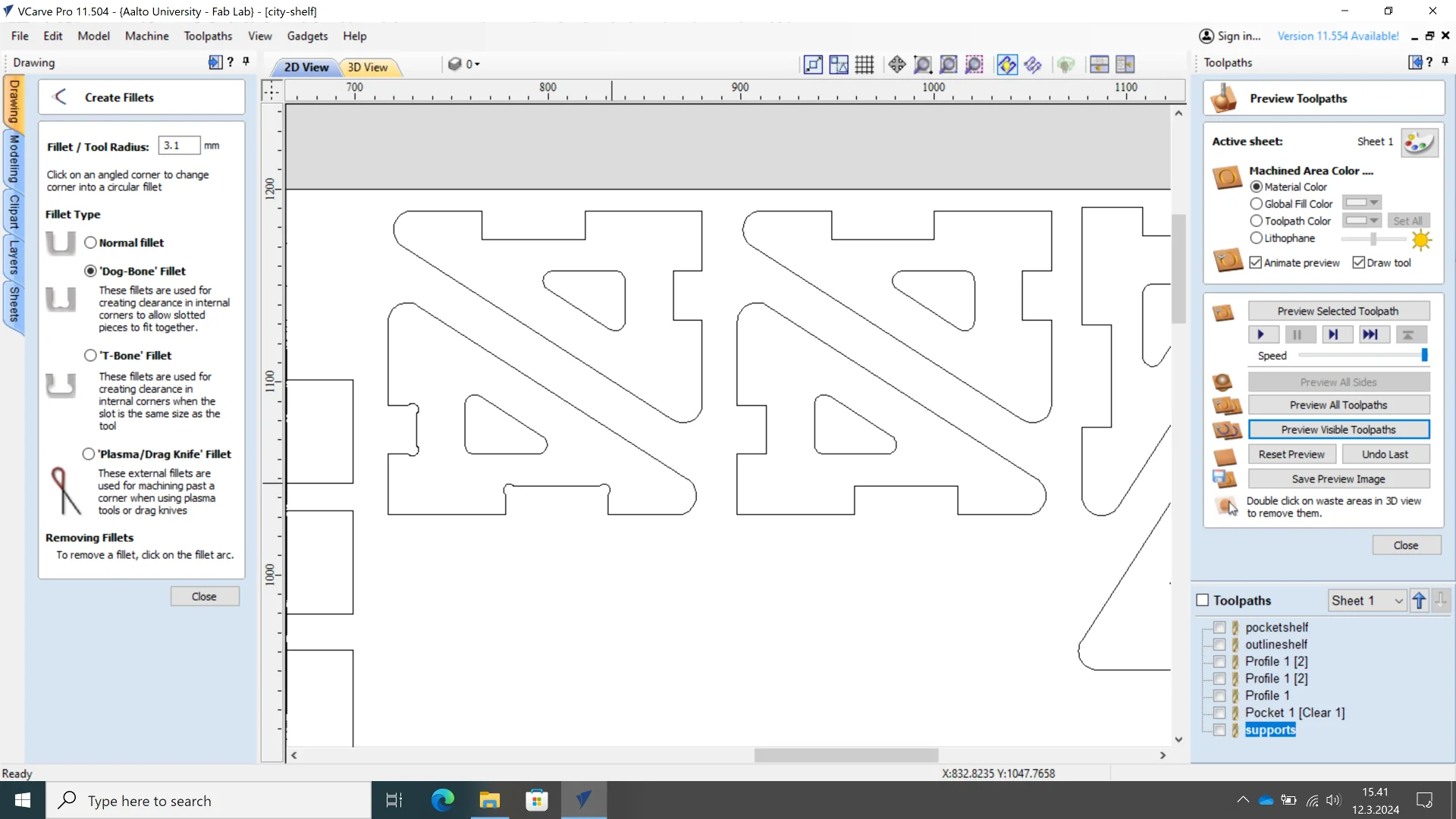
The paths could then be previewed by selecting the desired ones and clicking usually “Reset Preview” first and then “Preview Visible Toolpaths” to show the updated ones. Here it is good to check for everything necessary getting cut or engraved and that the tabs are created correctly.
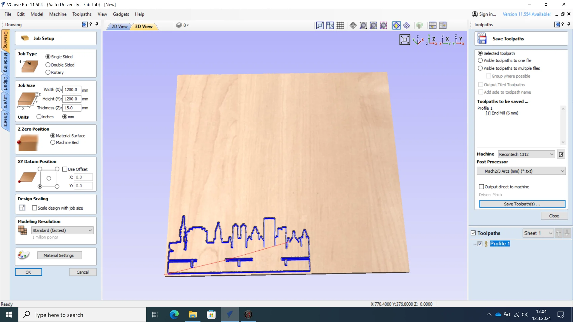
To save the toolpaths, navigate to “Save Toolpaths” and save them at any location. For a single path, the saving mode does not matter but for multiple paths one must be very careful. The checkmark in the box next to the toolpaths in the lower right corner means that they are visible, whereas the blue overlay of the text indicates selection, of which there can only be one. If one wants save multiple but not all toolpaths, make all visible by ensuring they have checkmarks next to them and choose “Visible toolpaths to one file” and then save with machine set to “Recontech 1312” and post processor to “Mach2/3 Arcs (mm) (*.txt)”. Neither I nor Solomon realized to do this for the second city background and thus only the outlines were milled. I decided that it was easier just to re-mill it using the correct toolpaths as I still had material left.
Milling
Turn on the machine by rotating the black main switch to “ON” position and pressing the red “Power On” button on the control unit. To use the entire vacuum bed, make sure that both handles in the front controlling their respective sides of the machine are pointing down. To turn it on, press the white button in the upper right corner of the control panel. You can tell if it worked by the noise but you can wait until you have finished the entire setup before you turn it on.
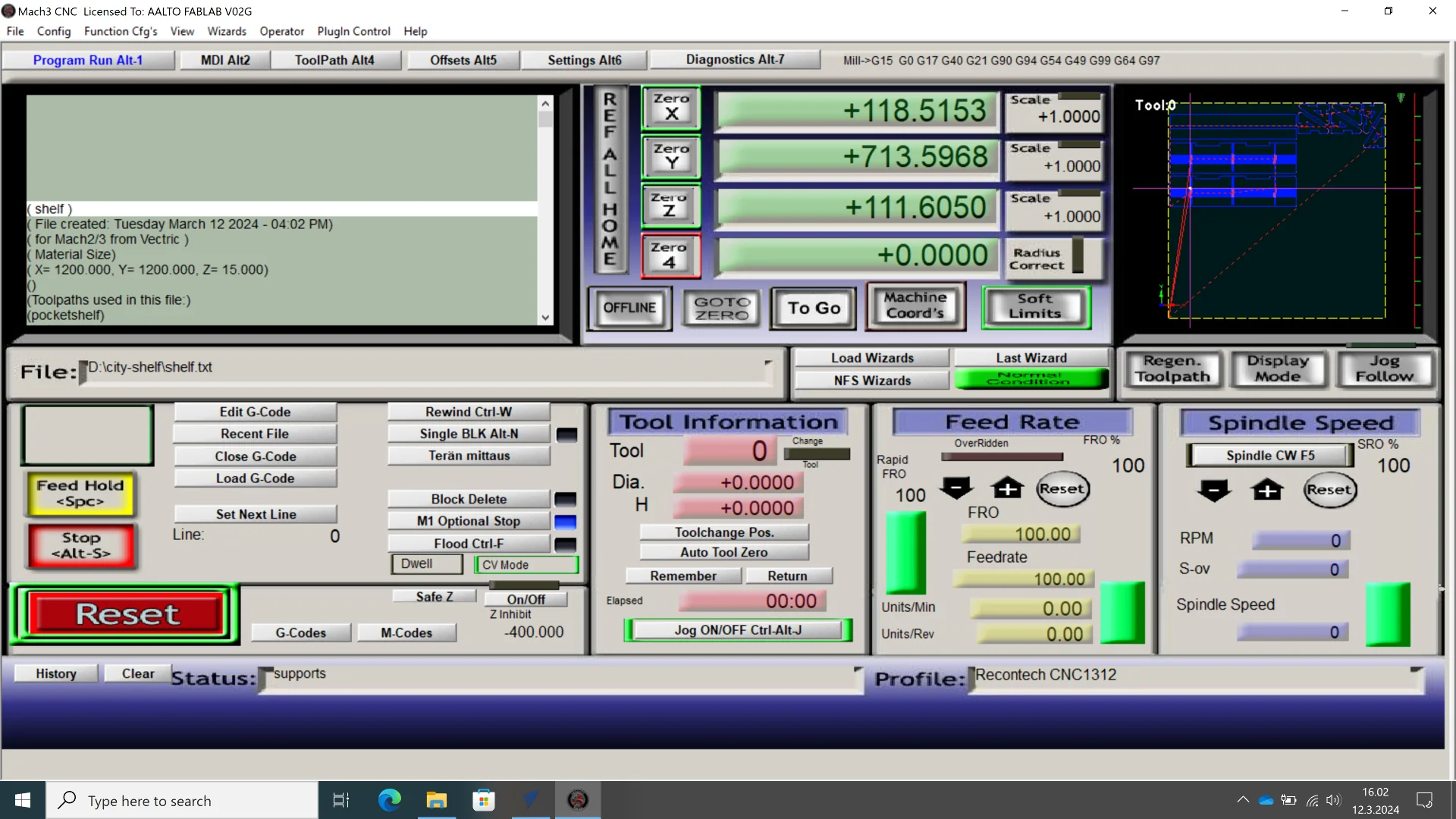
The saved toolpath file could then be opened in the very retro-looking Mach3 software via “Load G-Code”. Every time you open the software, make sure to begin by clicking “Reset” as the very first thing you do. Then, enable “Soft Limits” to enable software limits to make sure that you are notified if the toolpath exceeds the milling area. Finally, click “Ref All Home” to bring the tool to the origin in the front left corner. The tool can be moved manually using the arrow keys on the keyboards of both the computers inside and outside the room. You can then open the .txt toolpath file using the “Load G-Code” button.
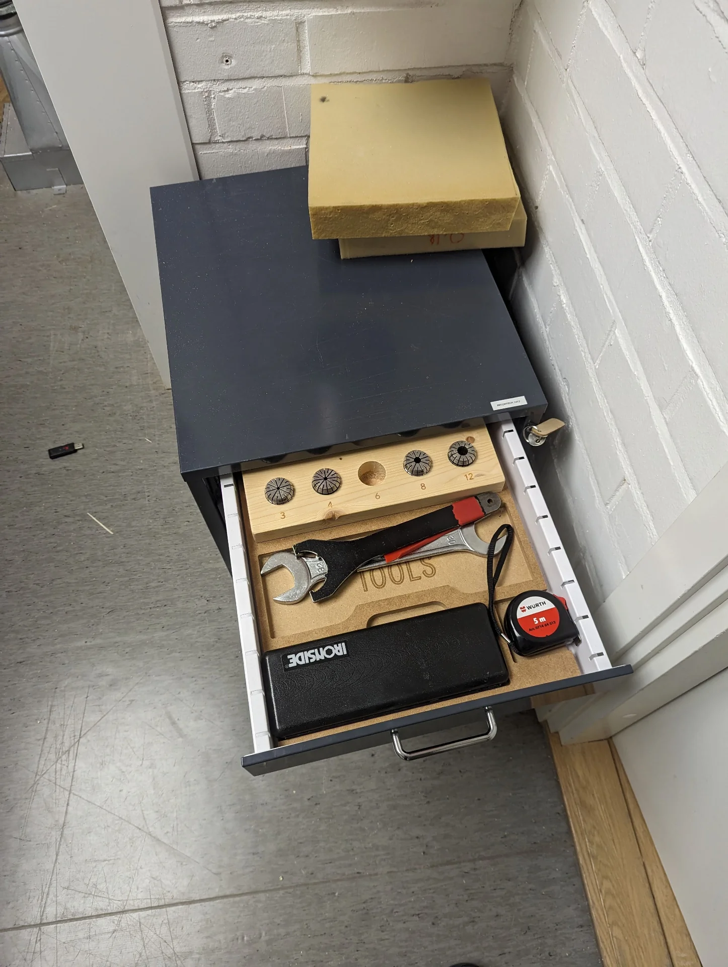
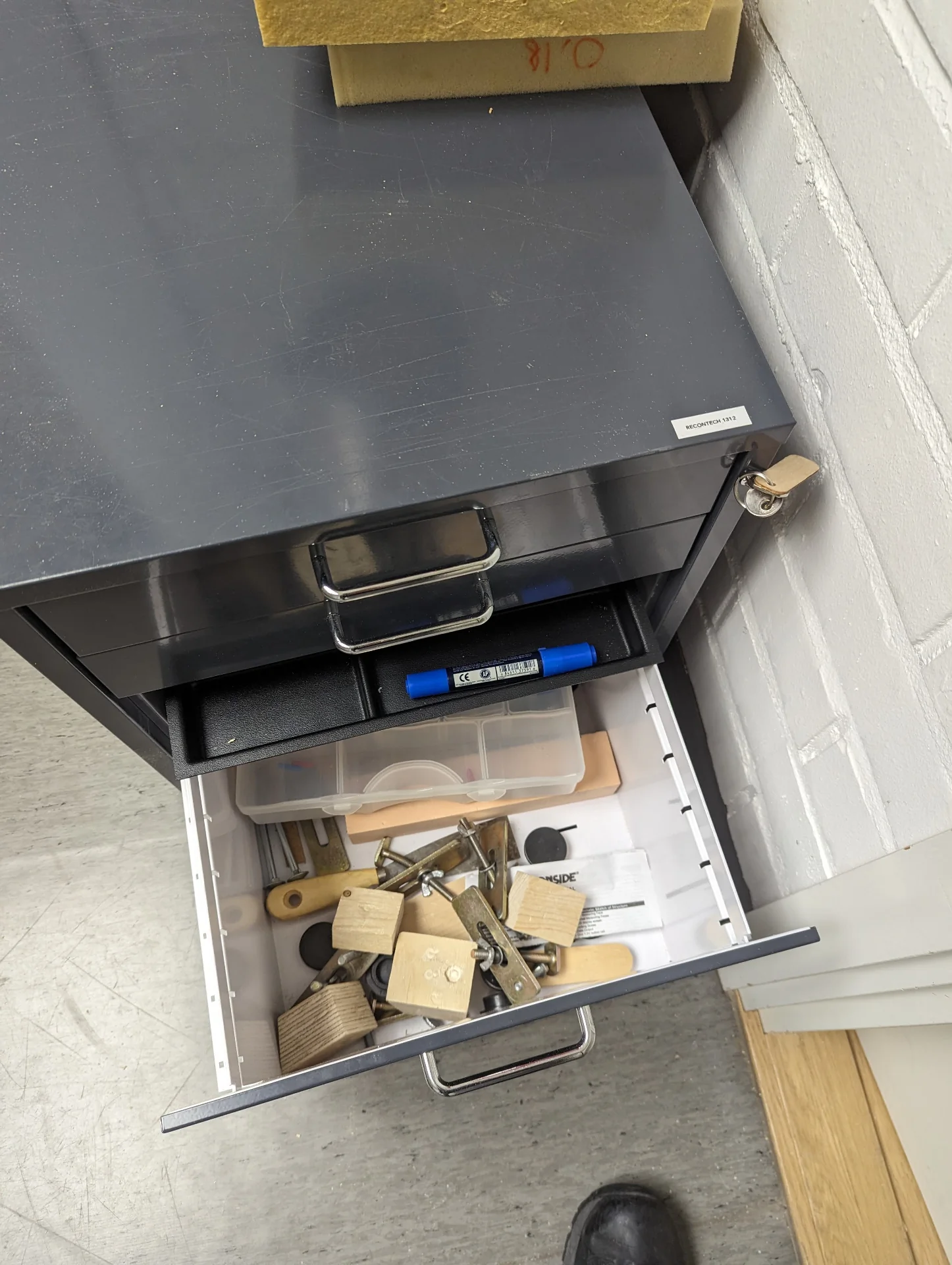
You can change the tool by first un-attaching the red dust shoe at the mouth of the large tube by loosening its two locking screws while holding it and swivelling it around the toolholder to get some space. Place the cushion found in the cabin immediately to the right of the door - where also the tools and collets are - under the toolholder to protect the tool in case it falls and change the collet by unscrewing the nut from the toolholder and screwing in another that is of appropriate size for the tool to be used. Insert the milling bit about 2cm in and tighten it by simultaneously using a spanner on the top of the shaft and a key wrench inserted from the bottom of the toolholder, bring back the dust shoe and remove the cushion.
To load the material, prepare the vacuum bed by unplugging the vacuum holes under the area to be covered and set rubber strips underneath to prevent the air from escaping. Place the sacrificial, breathable MDF layer on top and blow off potential dust with the air compressor on the left wall. If using the whole bed, open both vacuum valves and then place your material on top of the sacrificial layer. Turn on the vacuum and check that the suction is adequate by trying to push the corners of the materials and checking that the pressure gauge is on the green zone. If the suction is inadequate or the material has a risk of warping or vibrating or you just want to be sure otherwise, you can additionally fixture the material using clamps in the cabin that attach to the rails or by using screws/nails, glue/tape, weights or encapsulation depending on the material and your needs. Make sure, however, that these do not intersect the toolpath on any of the X-, Y- or Z-axis to not damage the tool.
To calibrate X, Y and Z, turn on the vacuum bed to suck in the material for an accurate height measurement and place the yellow, conical Z-axis calibrator magnetically attached to the left side of the machine on the sheet of material. Move the machining bit over it and click the “Terän mittaus” button in the Mach3 software, which slowly lowers the bit on it until it barely touches it and so automatically sets the Z-axis. Then move the toolhead into the desired XY position, which defines the bottom leftmost corner of the milling area, and click both “Zero X” and “Zero Y”.
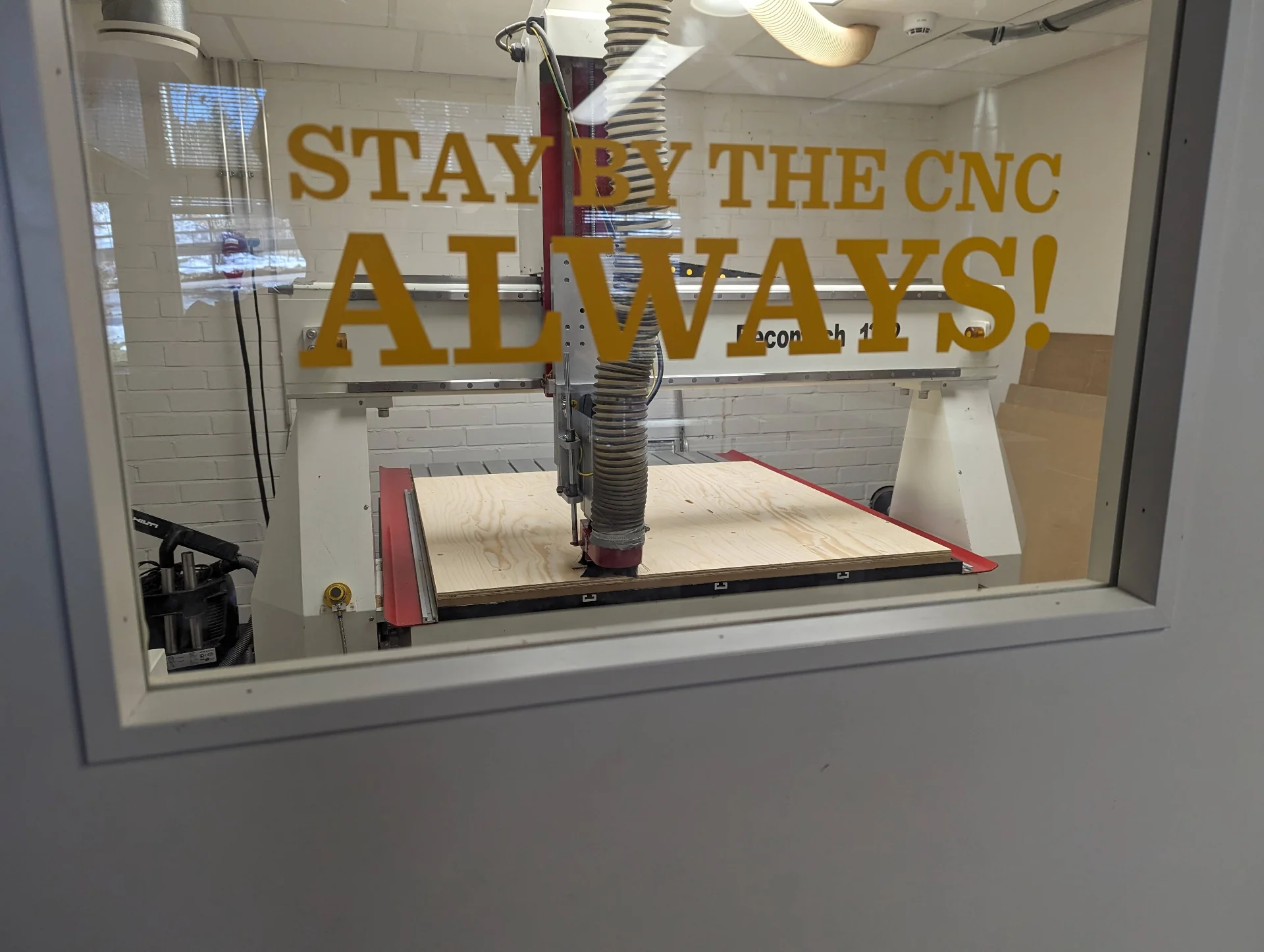
Once the tool and vacuum bed are set and tested and the material is loaded along with the sacrificial layer, you can step out of the room, close the door, load the G-code if you had not yet done so on the laptop outside next to the door, preview the toolpaths in the top right corner of the Mach3 software and press the green button next to the door to launch the process. The green light signifies that the spindle is not spinning whereas the red light warns of a spinning spindle. Opening the door causes the milling to immediately stop so do not ever do so without stopping it first or waiting for it to finish. Do, however, monitor the cutting outside. Wait for the milling to finish, clean up after yourself by performing the steps in reverse, always leaving the room better than you found it and take your freshly milled pieces with you.
Processing and assembly
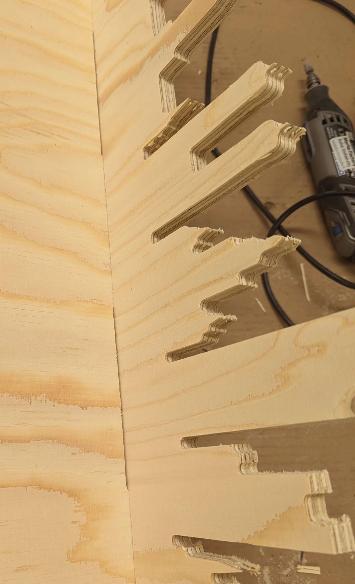
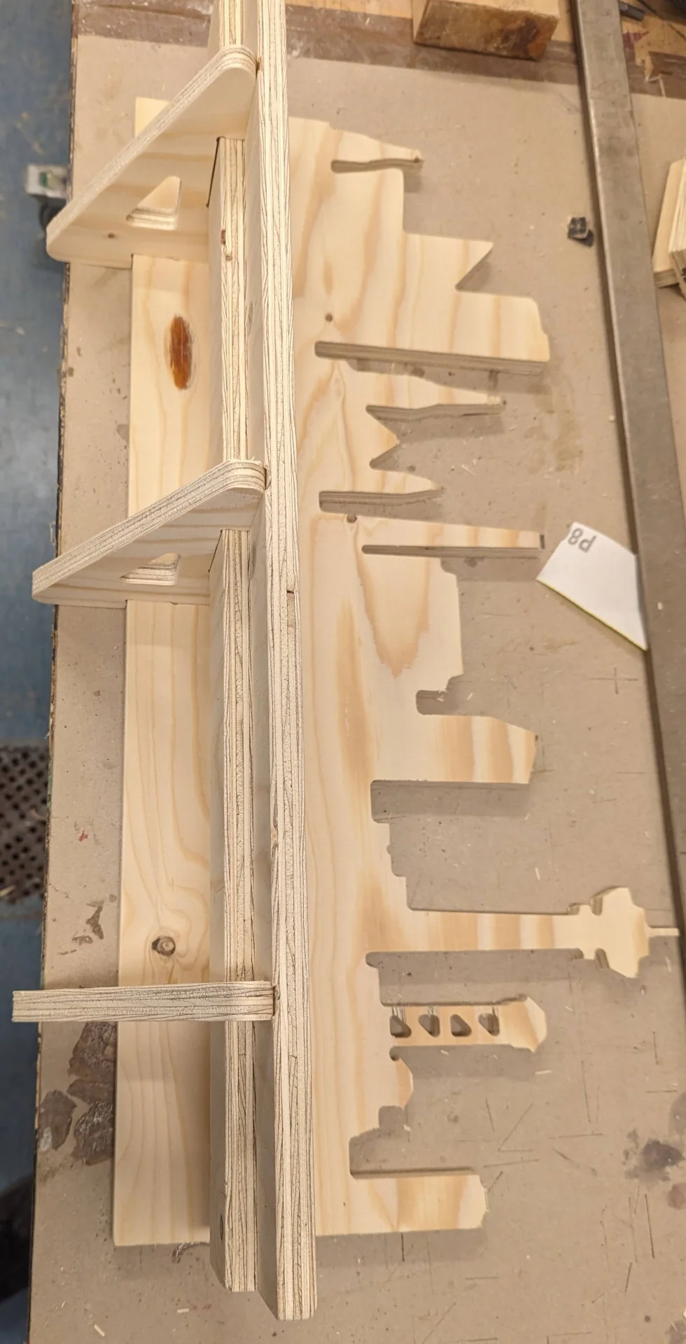
I carried the cut sheet of material to the woodworking space and used a chisel and a hammer to remove the tabs keeping the cut pieces attached to the sheet and the outcome was quite satisfying, even though particularly Tampere had some chipped details in Näsinneula and haulitorni.
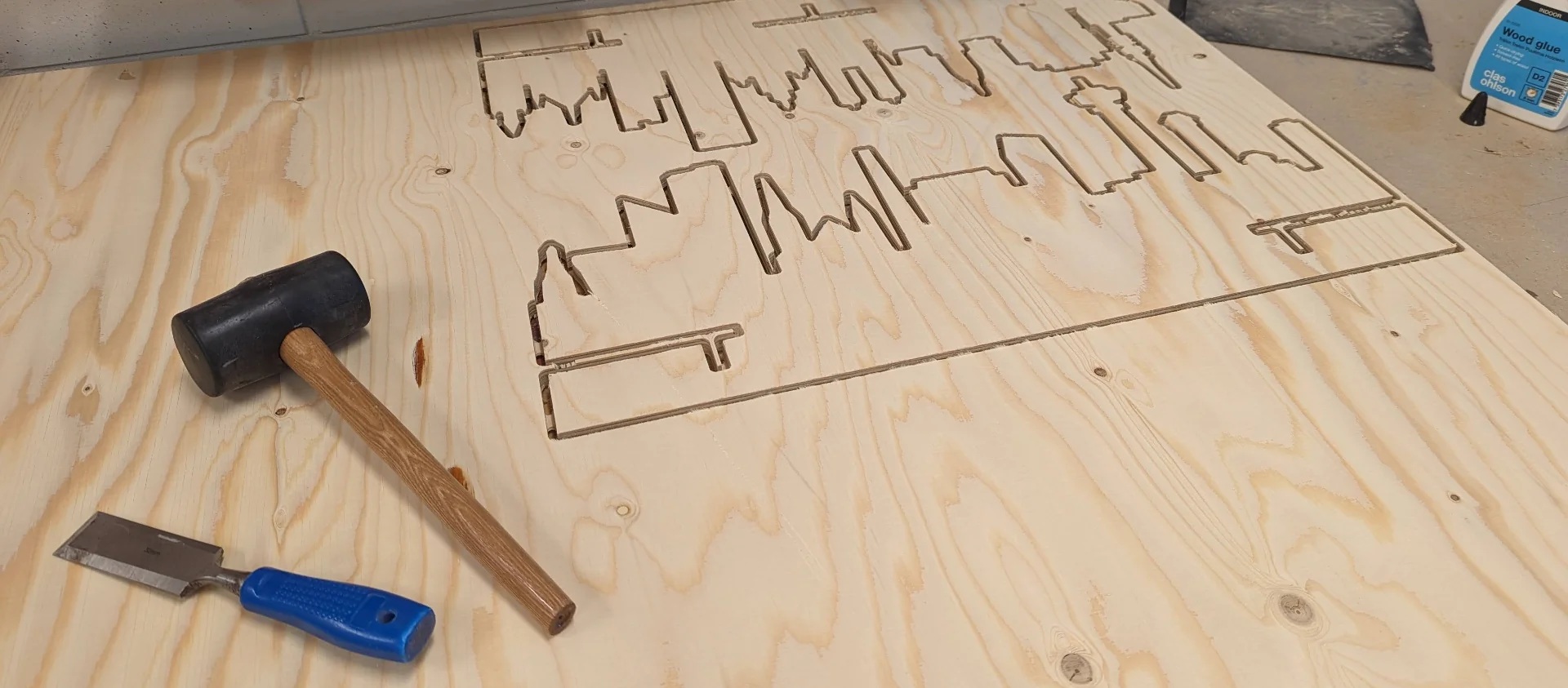
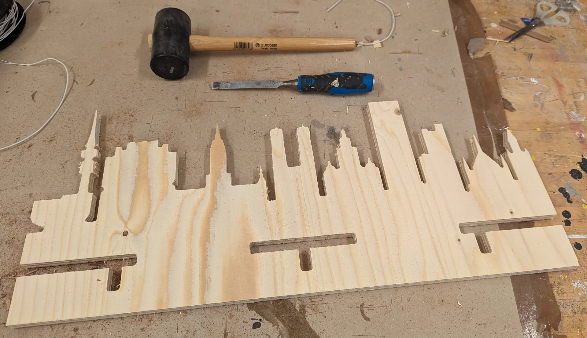
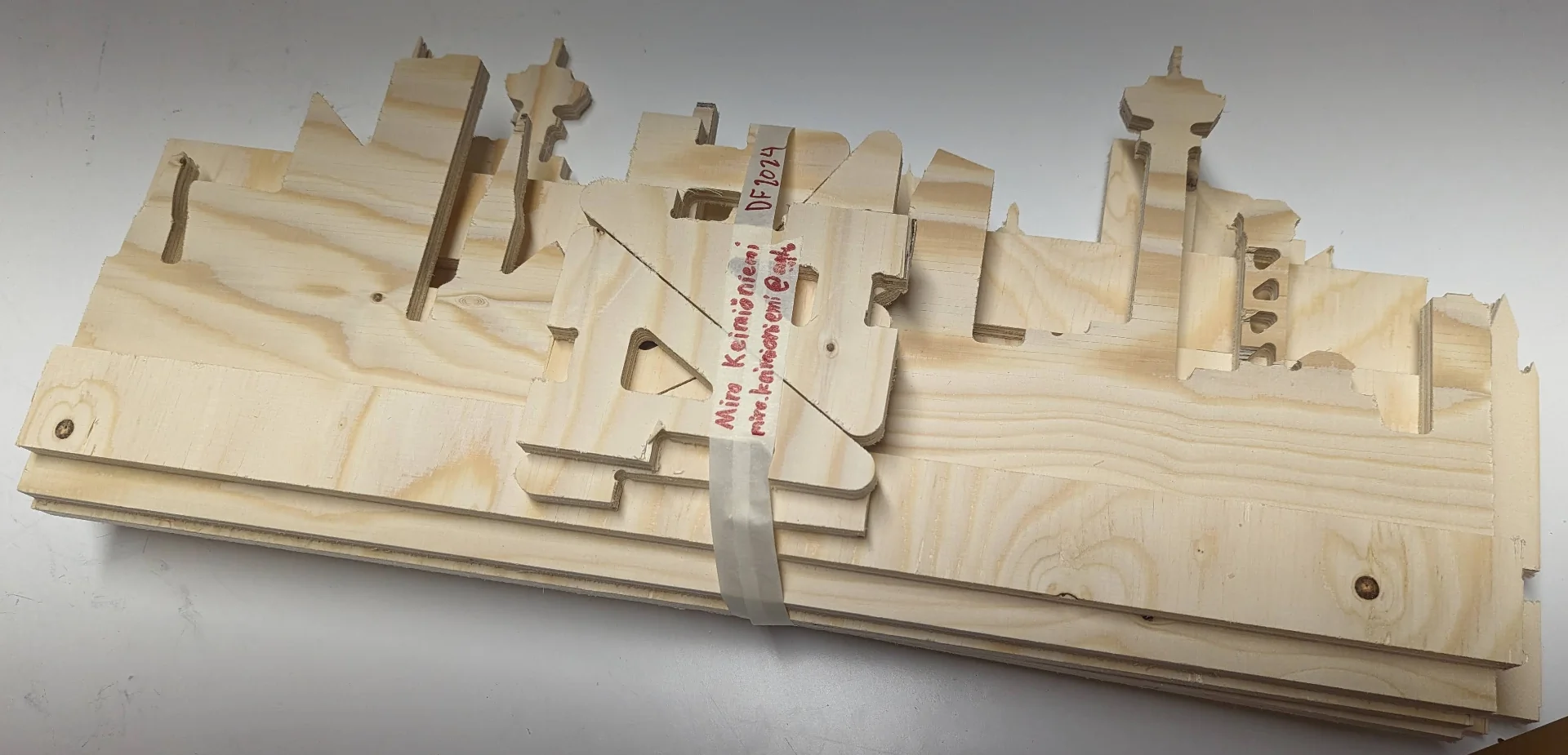
As mentioned above already, I forgot the dog-bones from the Munich joints and the first version of Tampere missed the center one entirely and I had to re-mill it. The Munich joints would have to be processed a bit more but hurry from various sources forced me to wrap up my work for a while before I got the time to return to it. Below are the products of the day of milling.
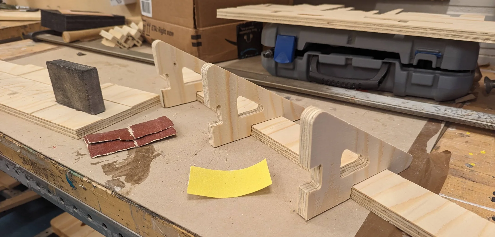
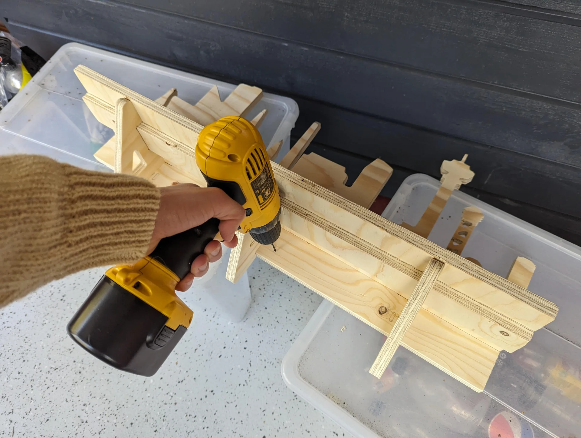
After a couple of weeks I finally got the time to go back and assemble the parts. I took Rosa with me as she was the one who wanted two and so we assembled one each with a bit of cooperation in drilling. I did Tampere and she did Munich. We sanded the parts to get rid of splinters, smoothen all corners and make them fit nice and tight.
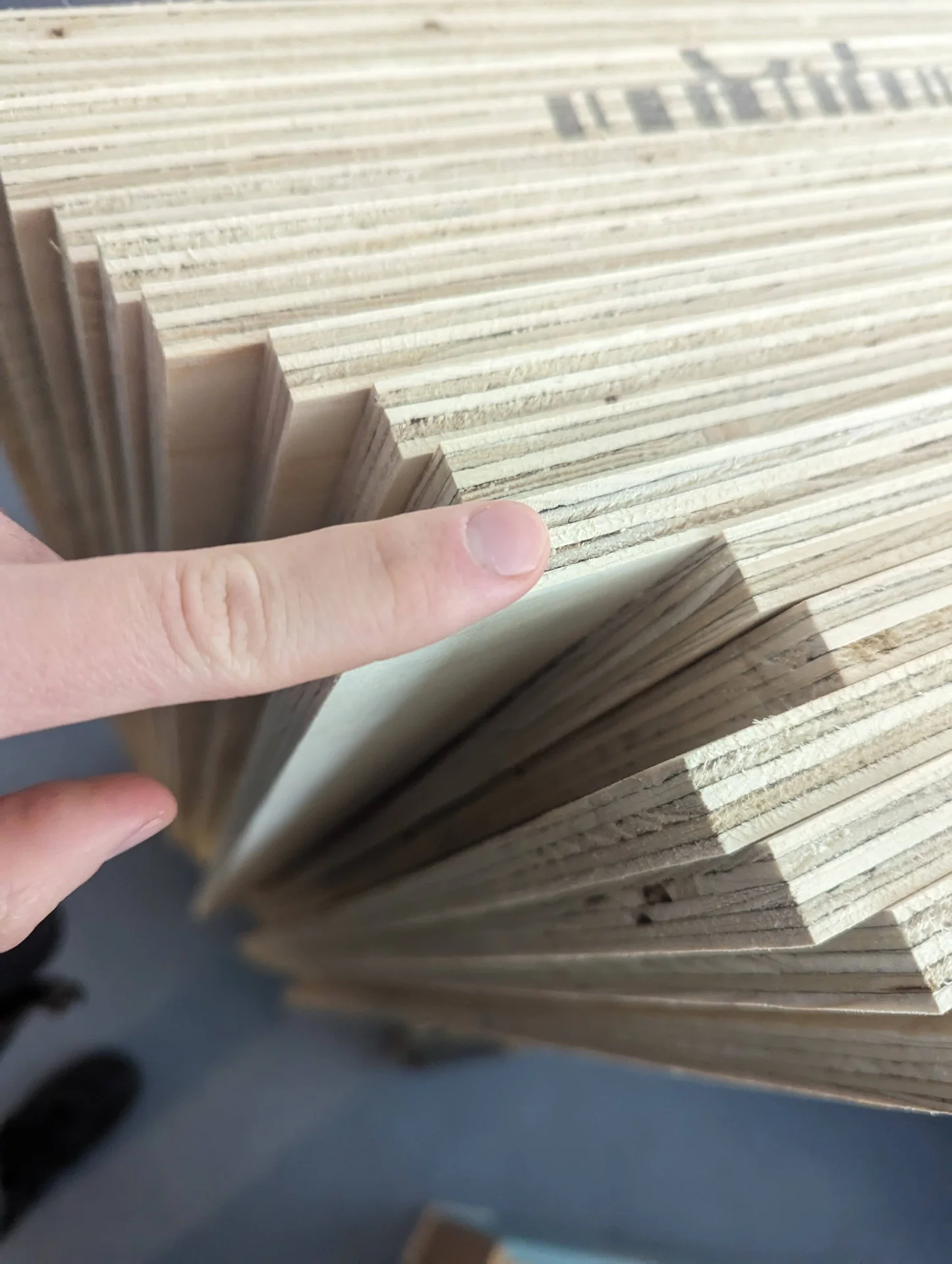
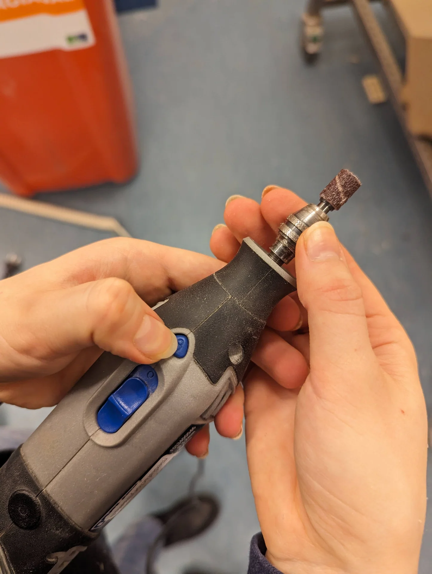
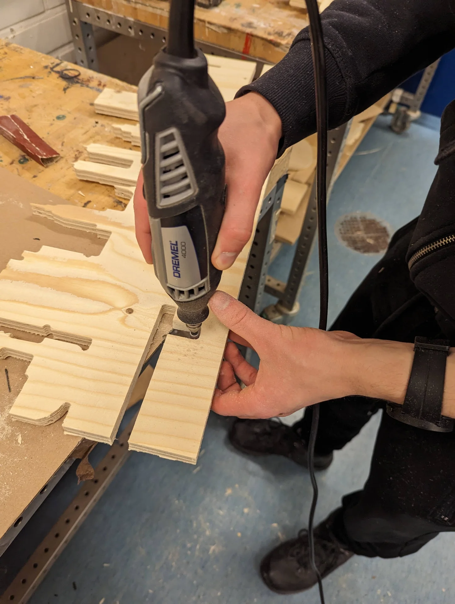
As already mentioned above, I forgot to add the dog-bones to the Munich background and thus the shelf part would not fit to it. We thus used the Dremel 4000 rotary-tool to add them afterwards. We changed the tool to the smallest sanding one available, although this was still quite a bit larger than the pre-existing dog-bones in the other parts. The tool could be changed by pressing the lock button and loosening the collet as shown below on the left.
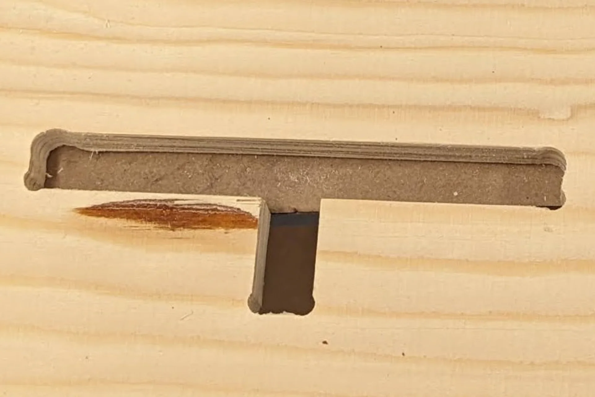
Using it was then as straightforward as plugging the power cable in, selecting the rotation speed from the bottom and pushing the blue switch up. Props to the designers for color-coordinating all controls blue nicely! The speed had to be set high enough so that the tool would not bounce and then I just gently pushed it into the corners where I wanted to create the dog-bones. The result can be seen in the rightmost image below, where the ones created with the Dremel are above and the pre-existing ones of the second Tampere background are on the bottom.
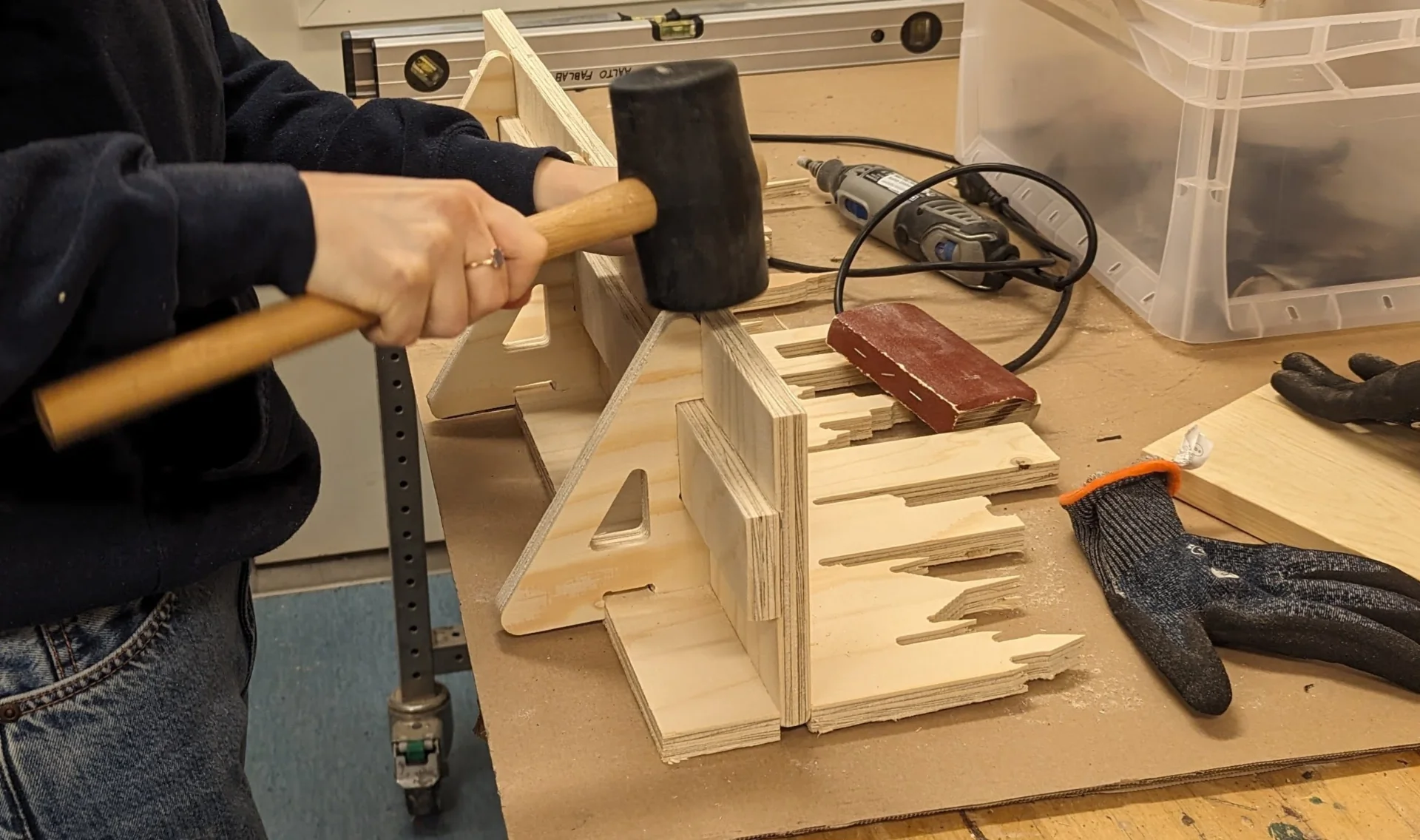
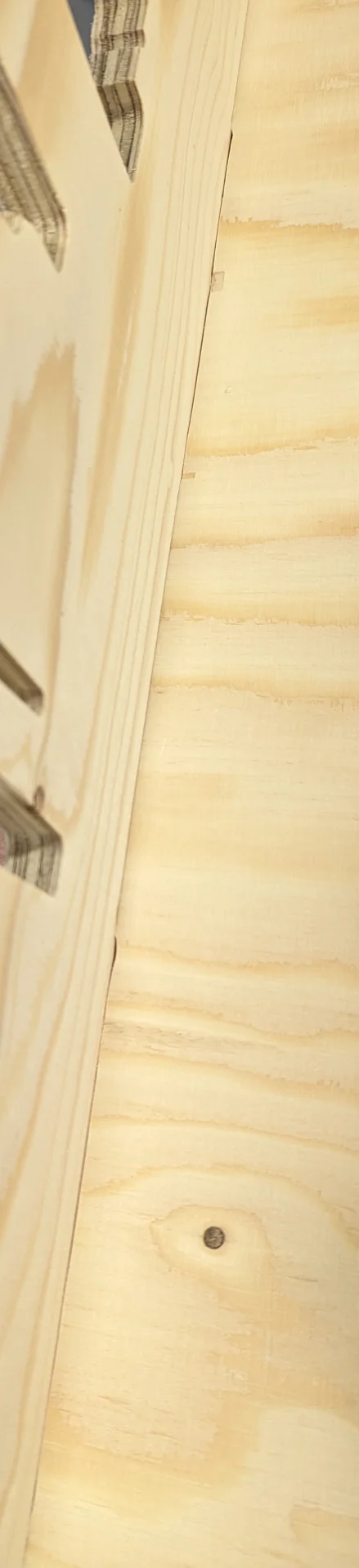
Rosa was actually faster than I, even though she had to make more additional dog-bones than I, and while I still sanded my pieces, she had gotten hers to fit already and was hammering them into place with the rubber mallet. The fit was really snug but she faced another issue, which was that the shelf part did not go all the way in, even with the hammering and there remained a small gap between the joints of the background and the shelf as the shelf part did not have dog-bones either, which we had overlooked. We tried further sanding it a tiny bit and then just pounding it in as far as it goes as it was so tightly and deeply in already that pulling it out would have been very difficult and likely loosened the fit for the next time and the result can be seen below on the right. It’s not perfect but close enough, particularly for the upper, less load-bearing shelf.
Trying to learn from this, I made sure to try and sand the corners of the shelf part so that they make true 90° angles. I tried to avoid creating dog-bones by only using sandpaper and the block as I wanted the fit to look perfect but in retrospective, it would have been easier to just create those as the gaps were not still quite perfectly closed although a bit better than without.
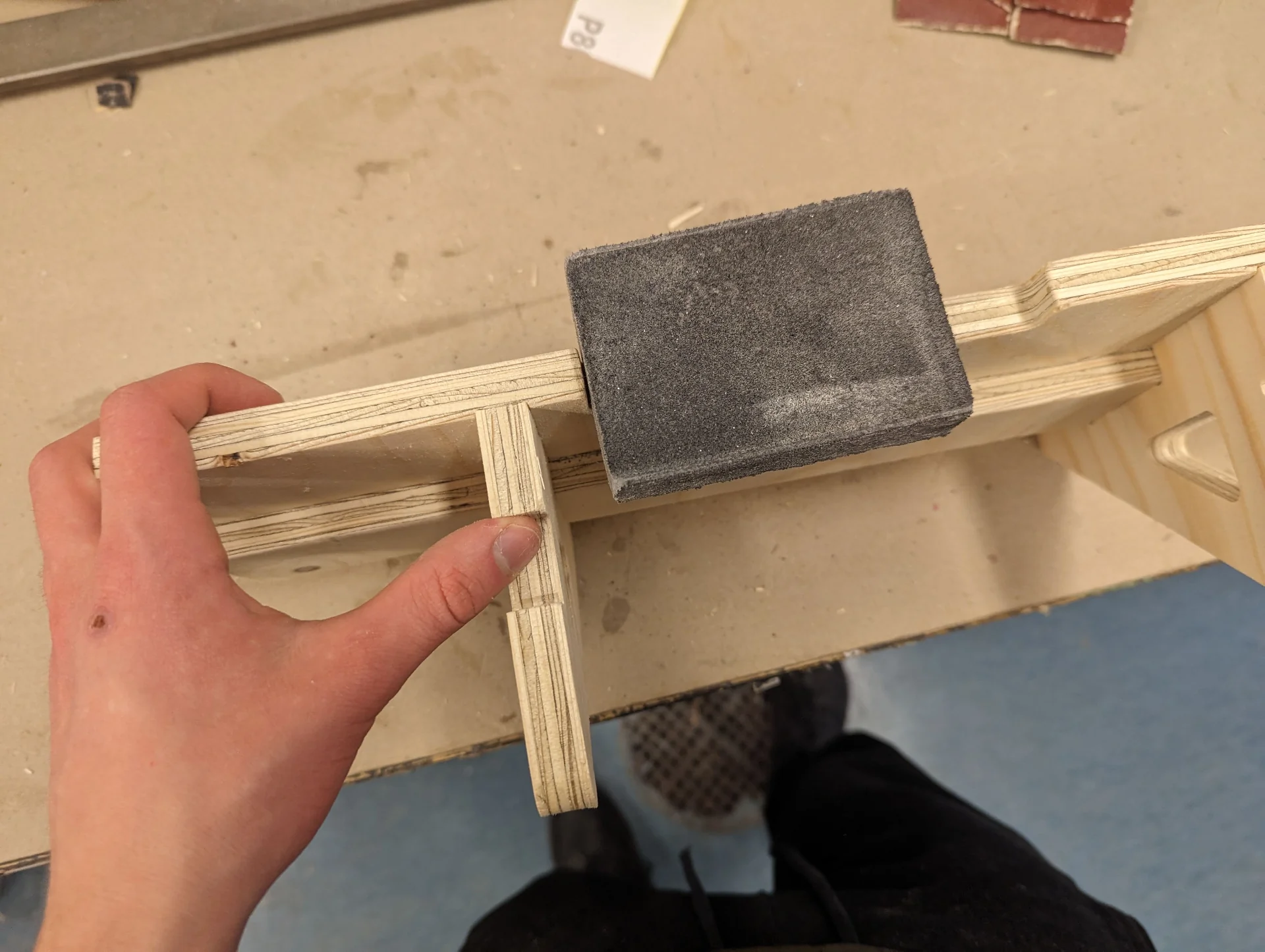
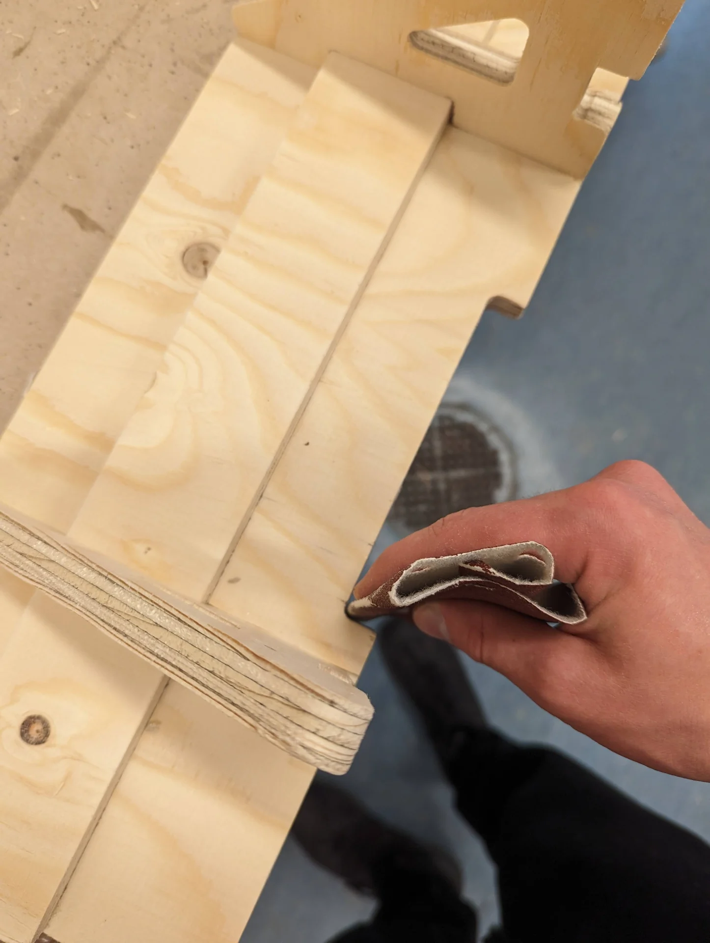
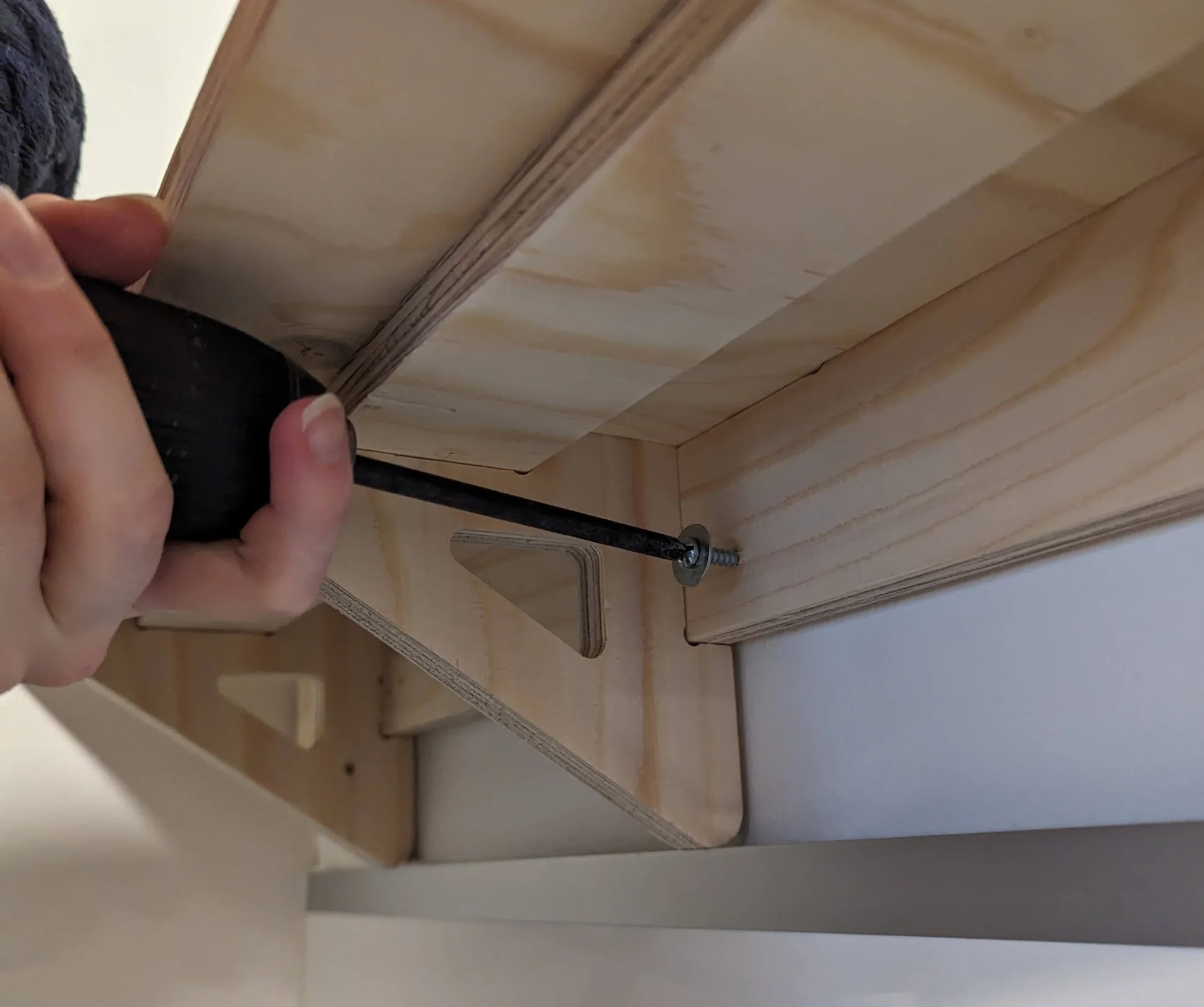
My parts slipped right in and while snuggish, not nearly as tight as Rosa’s. This meant that they were easier to work with but perhaps slightly less reliable in terms of staying together. To play it safe with both shelves, we decided to still tighten the shelve parts to the backboards with some screws, which provide just a bit of additional support and ensure that the parts cannot be pulled apart. The thin screws, chosen to avoid splintering, sunk in like butter to the very soft wood and could be nicely hidden on the backside.
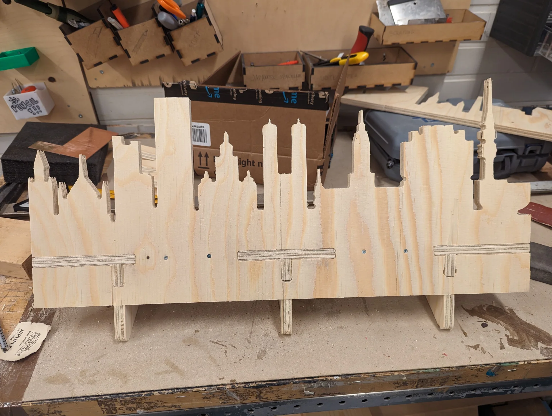
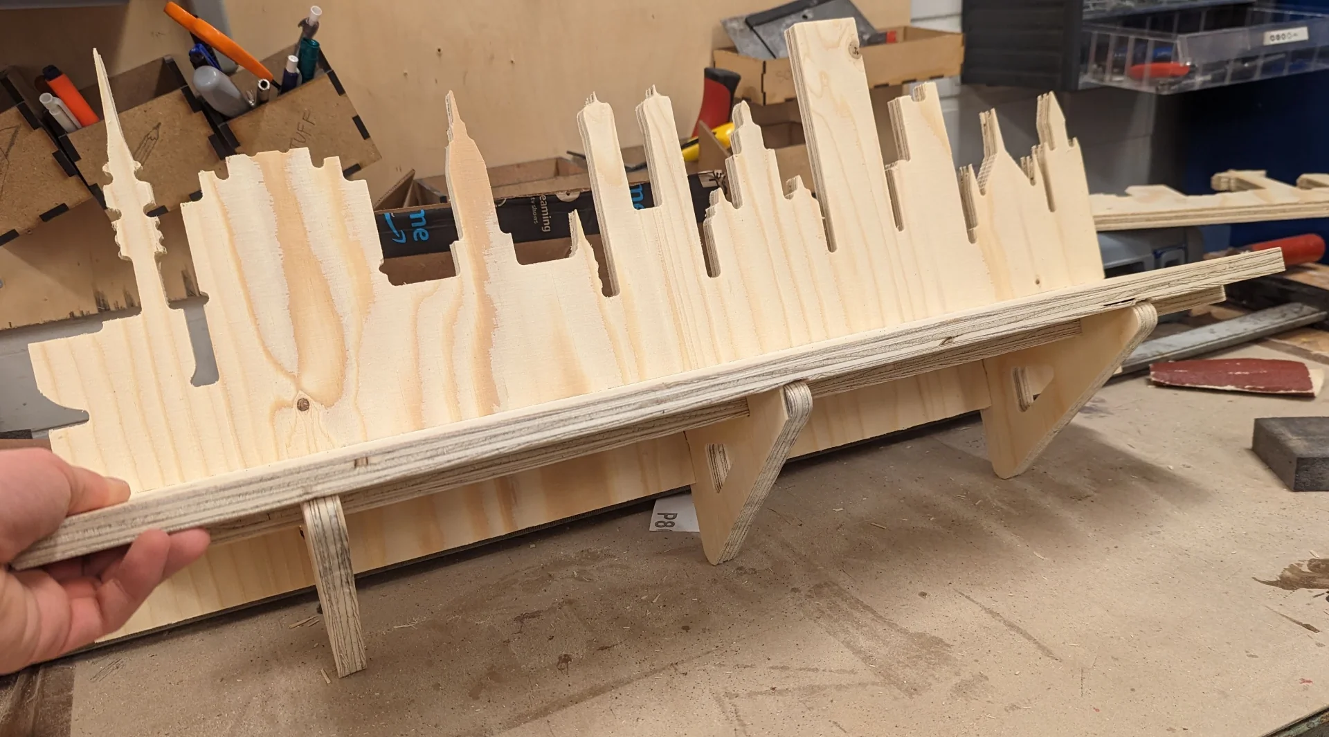
Below is a visualization of what the shelves would look like on the wall. I placed the lower Tampere shelf on top of the metal trim of the kitchen backsplash for a bit more of additional support as the contents of the shelf were to be quite heavy. I aligned the visible ends to be parallel to the edges of the wall and placed the shelves quite far apart to make sure there would be space for the tall containers on the lower shelf, although when actually fastening them, I brought the upper one lower.
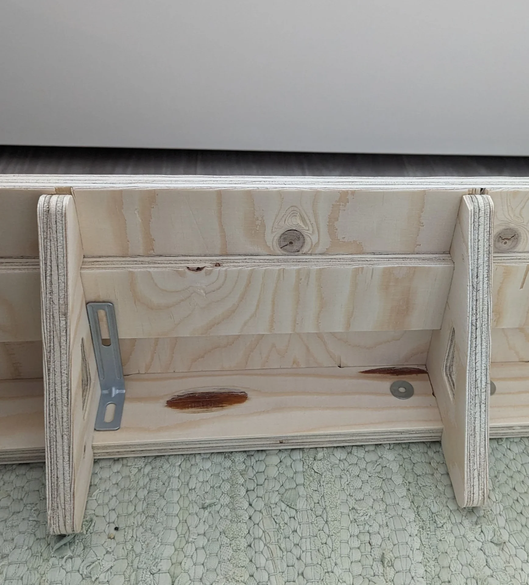
To then install the shelves, I marked spots for pre-drilling holes into the backboards of the shelves for the screws used to fasten the shelf with excess plates from assembling IKEA furniture - of which there were precisely the right amount. The backboard was made to be elongated precisely so that most screws could be “hidden” under it but for extra stability and safety, I added ones above as well, centering them on the buildings closest to the edges high enough to significantly increase stability but low enough not to look too out of place.
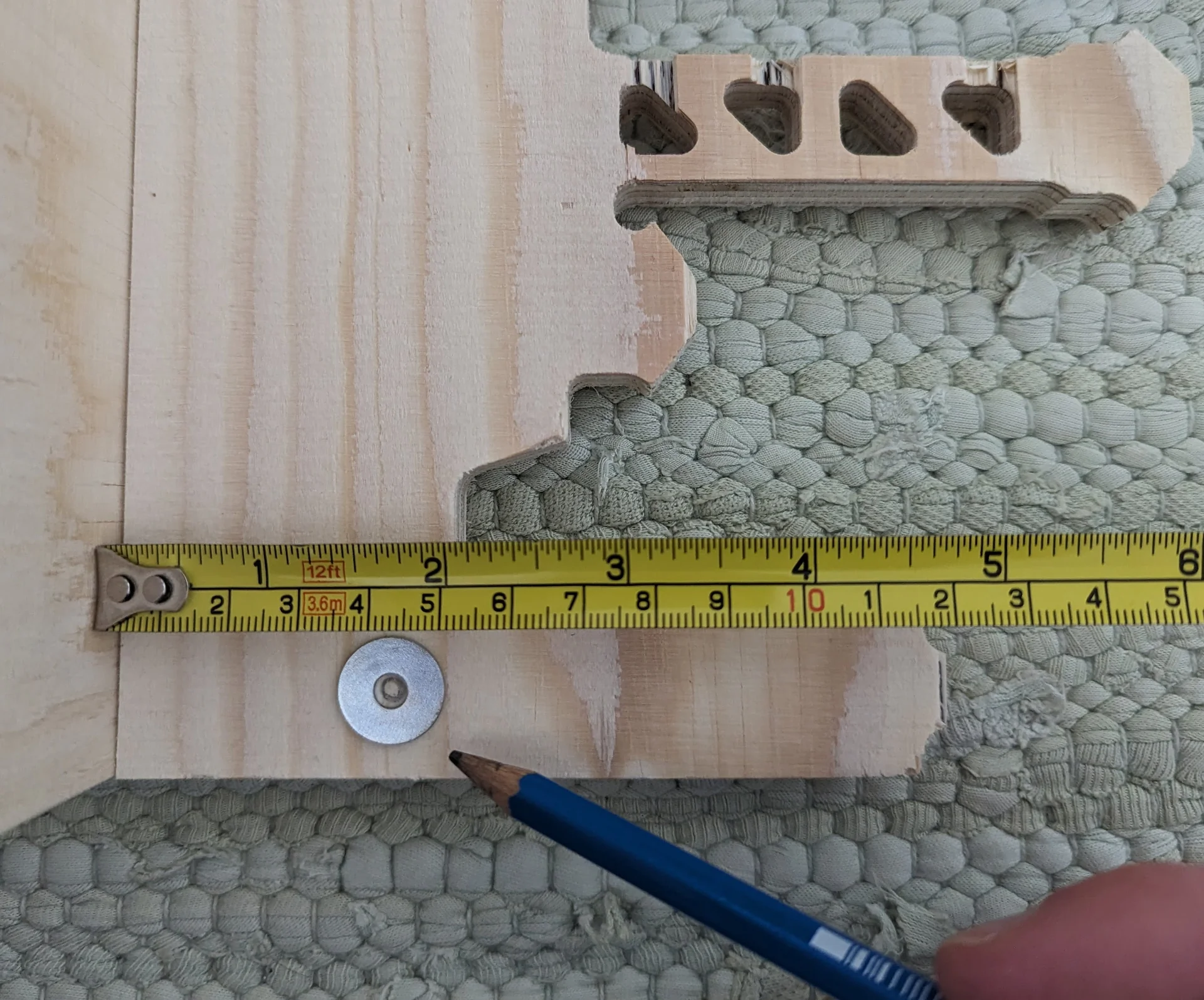
I measured them carefully and did the same for the ones under the shelf as well until I realized that it was a lot simpler and faster just to set the drill perpendicularly against the backboard as close to the underside of the shelf and its supports as allowed by the drill’s shape and just drill straight through with a thin drill bit. Here it was important to be as close as possible to the shelf and support components to impart as little stress on the wood as possible from future loads but this was limited by the drill’s shape and size.
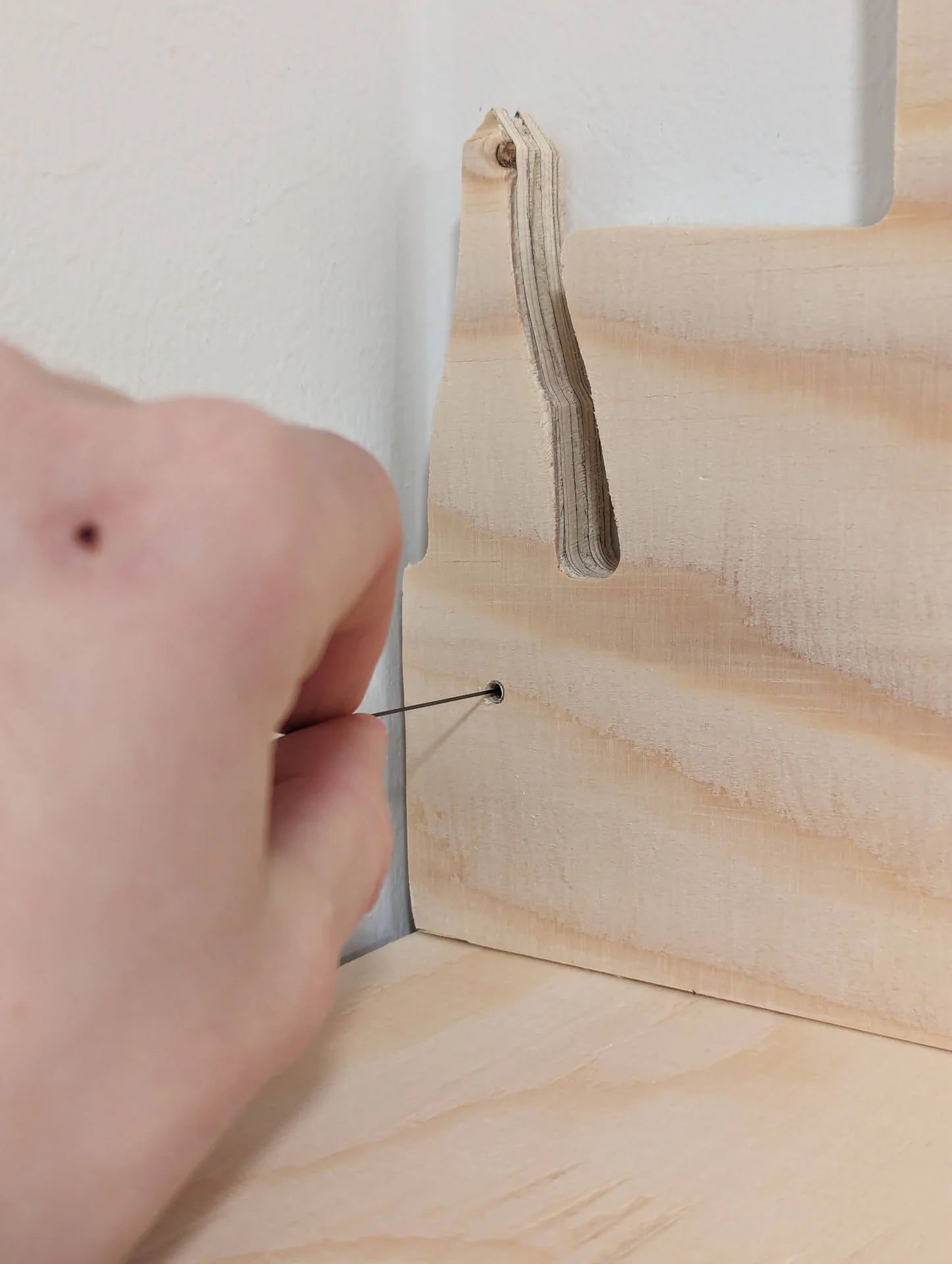
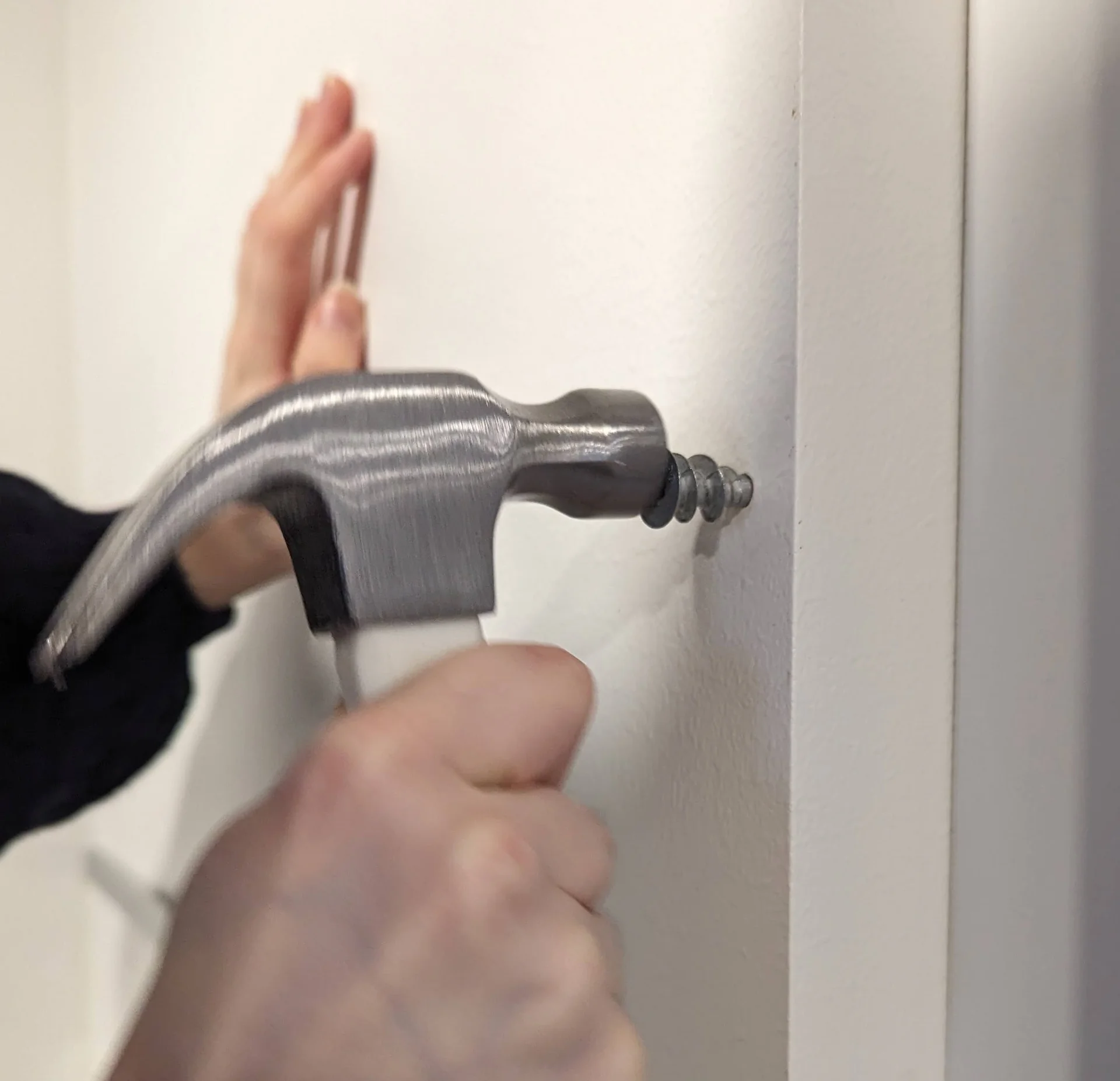
The wall where the shelves were to be installed was drywall and thus required drywall anchors for safety and stability. Rosa held up the first shelf while I marked the spots for the centers of the anchors by drawing through the holes with a 0.5 pencil lead as they were the only things slim enough to fit through. It worked neatly after cleaning the splinters on the backside and I then installed the drywall anchors by first hammering them in a bit and then tightening with a basic screwdriver. Many anchors broke inside the wall so that their tips had to be carved out with a smaller flat-tipped screwdriver before inserting a new one in their place and continuing from where they were left off but we had enough for this to not be a major issue.
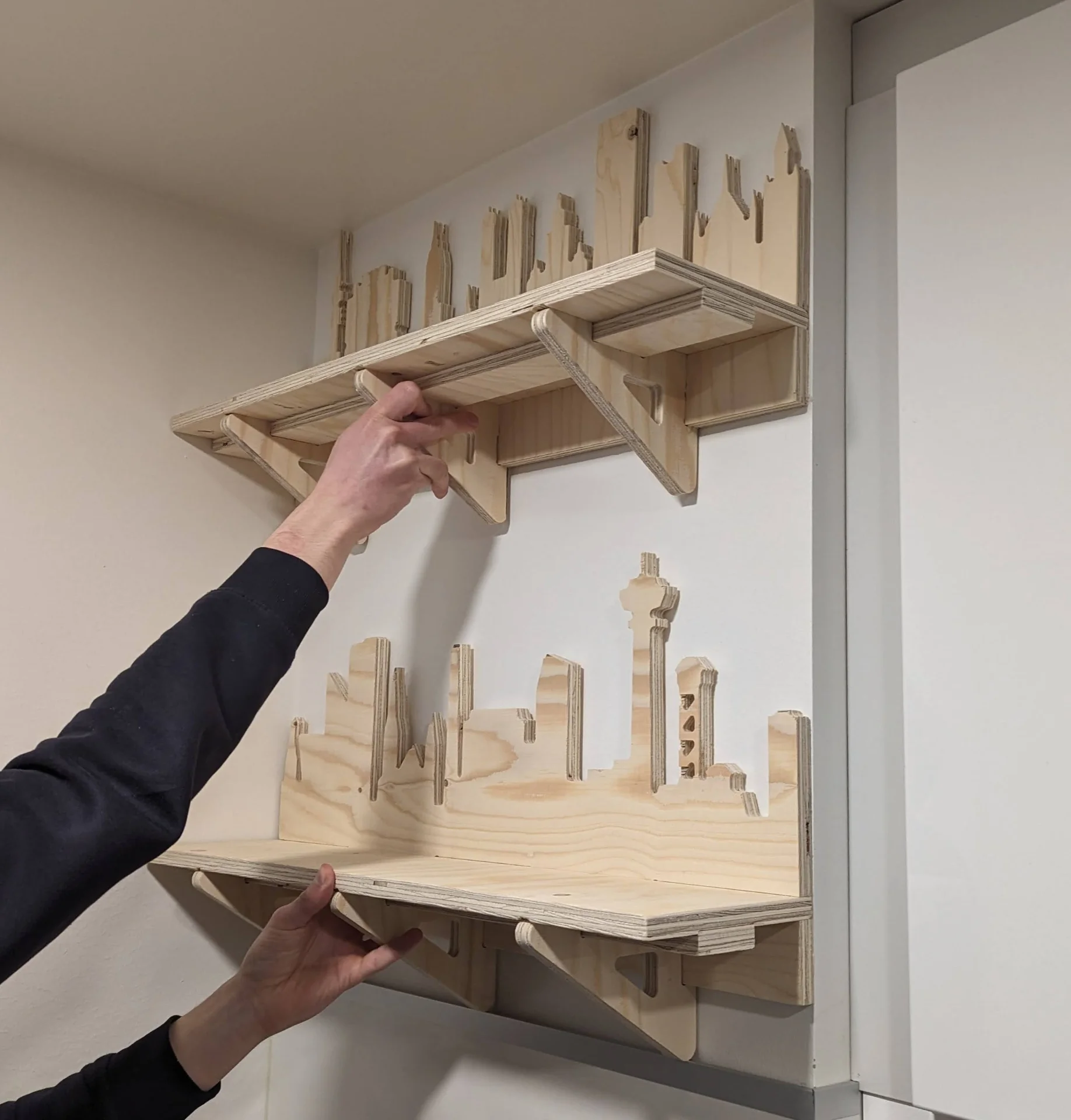
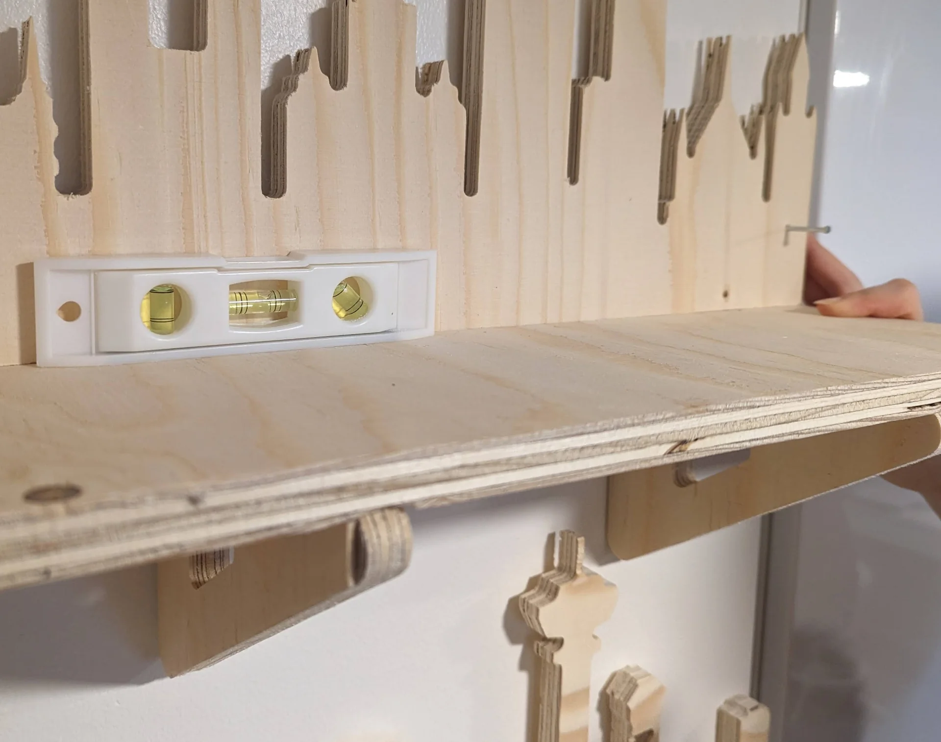
We then drilled the screws in with the backplates, which went surprisingly smoothly without any major trouble. To position the second shelf above the first one, I placed the tallest container that the lower one was meant to carry on it and left a couple of centimeters of space between its top and the bottom of the next shelf. Simultaneously we had a leveler on the second shelf and once it was both at the right height and perfectly level, we drew a long line under the backboard to mark this and then Rosa marked the holes while I held the shelf still. Having been careful in the design phase paid off as the tip of Näsinneula avoided a collision with the support of the upper shelf nicely.
Drilling the second shelf to the wall was a lot scarier as we could not properly tell whether the holes were exactly on top of the anchors but we figured out that we could stick thin hammering nails through both the holes in the shelf as well as the anchors on the wall. We stuck ones through every hole we were not currently drilling in and so ensured that the shelf stayed level and in place while drilling. Starting from the far ends and moving towards the center, we soon had both shelves installed.
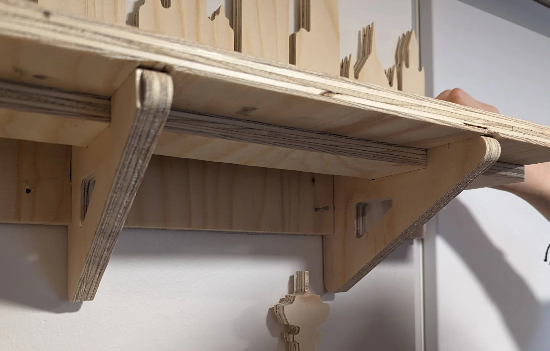
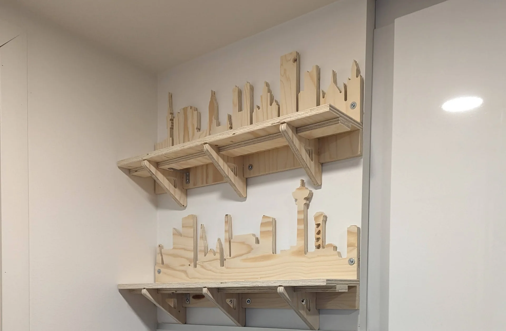
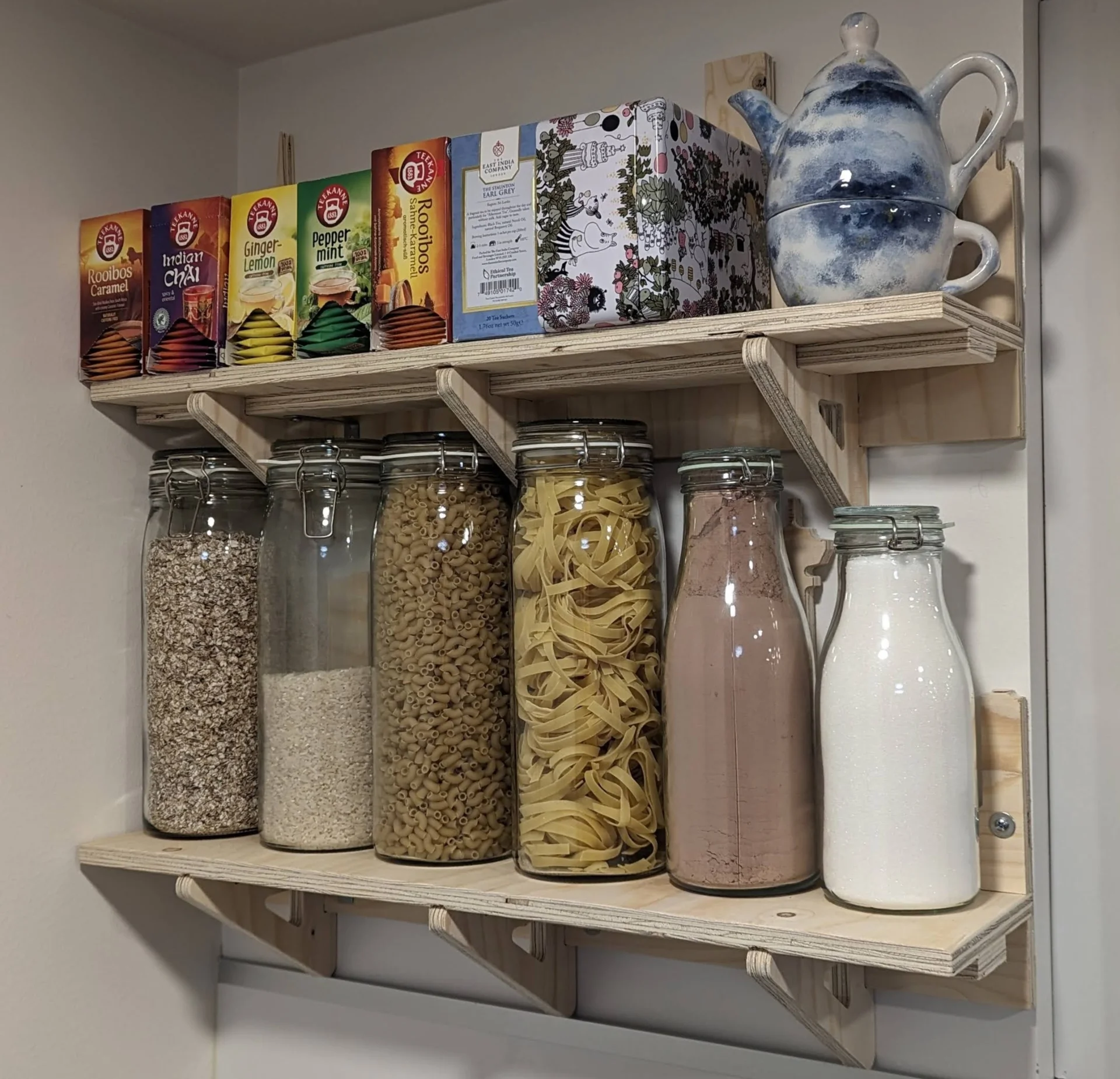
Below are the shelves in everyday usage. Not much of the city backgrounds can actually be seen outside of a tea ceremony when all our tea varieties and Rosa’s self-painted teapot + mug combination are offloaded from the shelf but they fulfill their functional purpose perfectly and presented a nice challenge in making them. I was very relieved after they easily carried all the weight of the full large containers.
Reflections
This was an intense week during which I learned not to trust Ondsel with vectors but also how to create more complex parametric designs, mill them and how to save as much headache as possible in the post-processing and assembly phase.
Firstly, one must be very deliberate with their choice of parameters and their relationships. It would be a good idea to note the possible ranges where the parameters can lie or to define only a very small number of base parameters from which all others are derived in a way so that they can range from 0 to infinity without interfering with the others. Intuitively, the maximum number of such parameters would be 3 for width, height and depth. If there are any more, they will by necessity break down eventually, which might also be desired such as in this case with a fixed thickness, but this should be noted.
Once the design is made, there exists far smarter ways of exporting than exporting the dxfs individually. Next time, I would most likely create the toolpaths in Fusion 360 too or, at the very least, create a sketch of the surface of the material sheet with fixed dimensions and all the components laid out on it. I could then export this as a singular .dfx file, which would save all the headache in VCarve Pro, including both overlapping lines and accidentally not exporting inner paths.
Finally, the importance of Dog-Bones cannot be overestimated. Adding them to all the relevant corners upon creating the toolpaths saves a ton of effort from the post-processing and assembly phase. Also, be prepared for splinters, particularly with thin parts of the design and cheap wood.
Overall, however, I am proud of the result, which still holds its load well after a couple of weeks!