This week was super fun! The documentation, however, is not written entirely in chronological order because the threads of the different kinds of cutting were very interweaved due to introduction sessions and different velocities with ideation etc. It took me a while to come up with the idea for the parametric press-fit dragon construction kit, whereas the idea for vinyl cutting was almost immediate. Still, I got to test out laser cutting first for three pieces before being interrupted and moving on to the vinyl cutting. Nevertheless, I can confidently say that I easily spent the most time at the Fablab in the first few days of this week out of all my coursemates. Luckily the queue for the laser cutter was not usually too long when I was there.
Assignments:
- Complete laser cutter introduction and safety training and document the process in a group assignment page. One person from each group will be responsible for creating the group documentation repository/page.
- Add link to your the group documentation page/repository to your individual documentation.
- Design, laser cut a parametric press-fit kit. Please avoid making boxes with finger joints. It is going to be considered below minimum requirements. Material (cardboard, ~3.75mm thick) is provided. Material thickness should be a parameter for on-site adjustment.
- Use the vinyl cutter to cut something. It can be as simple as a sticker for your laptop to multi-color design for your t-shirt.
- Add a new page for the documentation of this week out your course documentation website.
Vinyl cutting
I started with vinyl cutting, because I got the idea for it immediately from the suggestion of a design for a T-shirt, although I would change that to a hoodie.
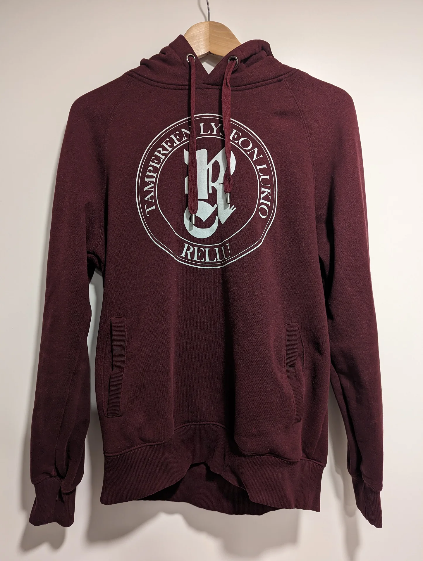
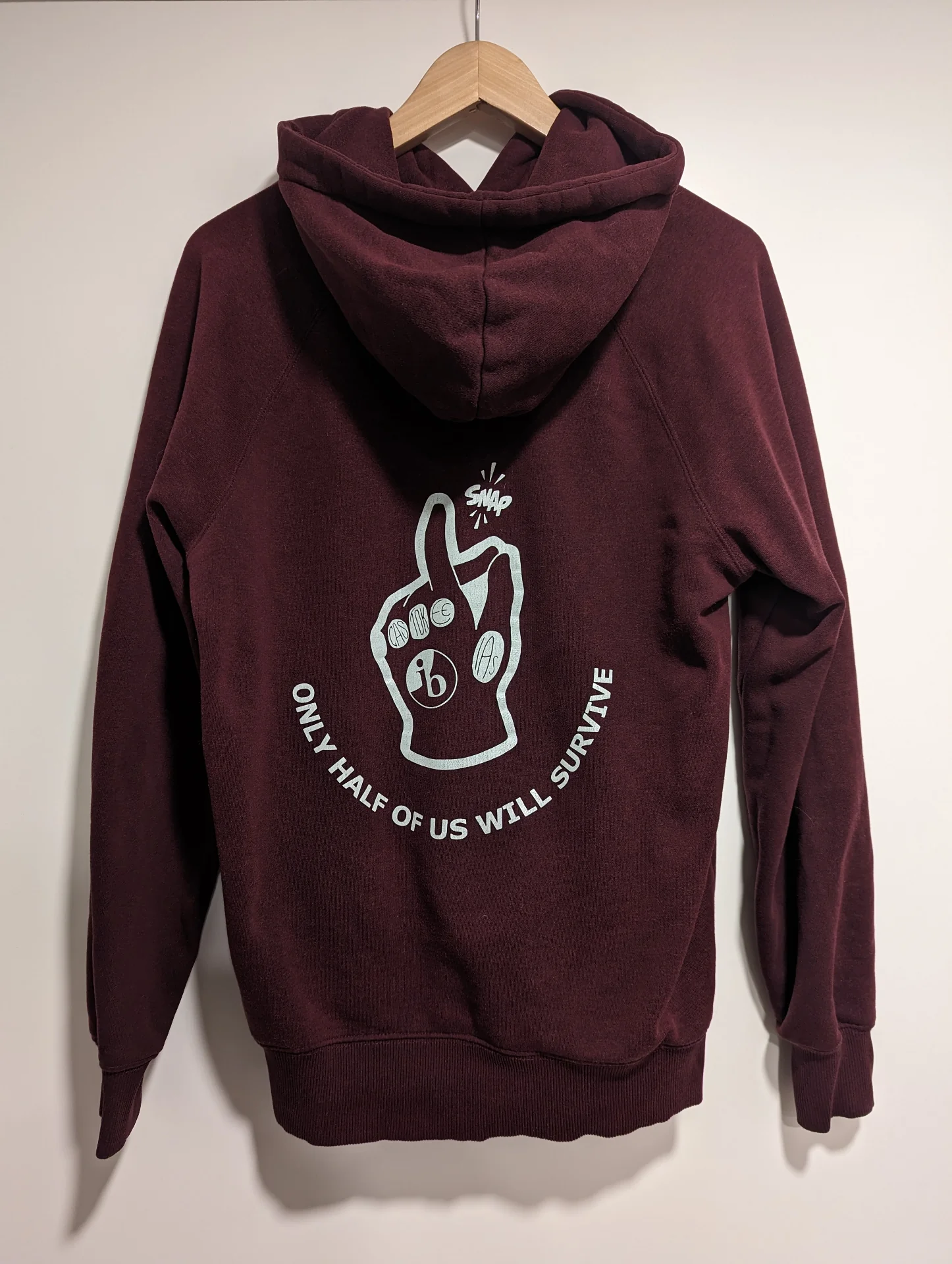
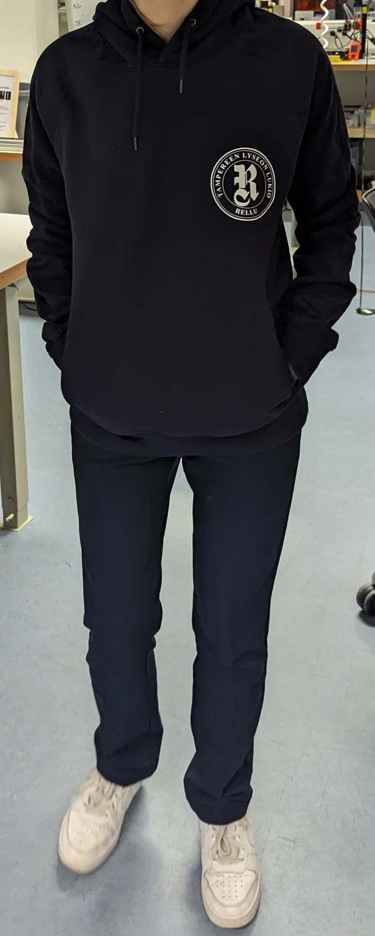
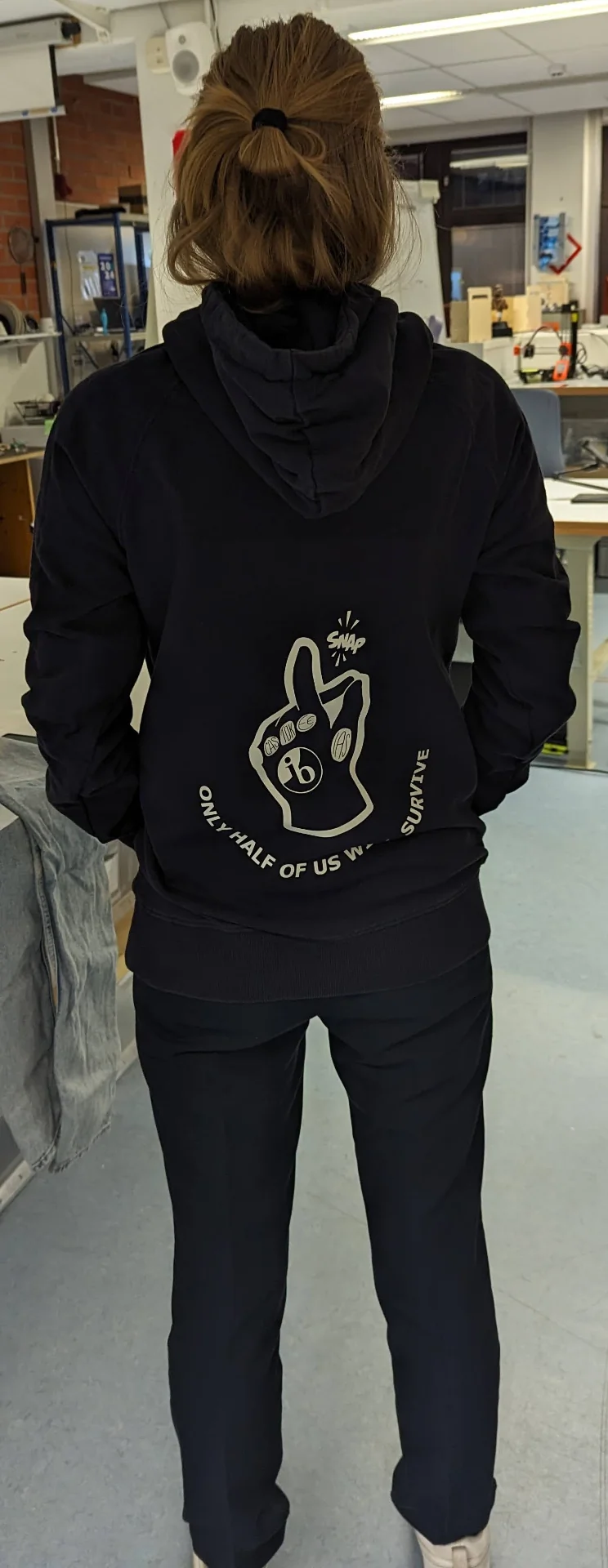
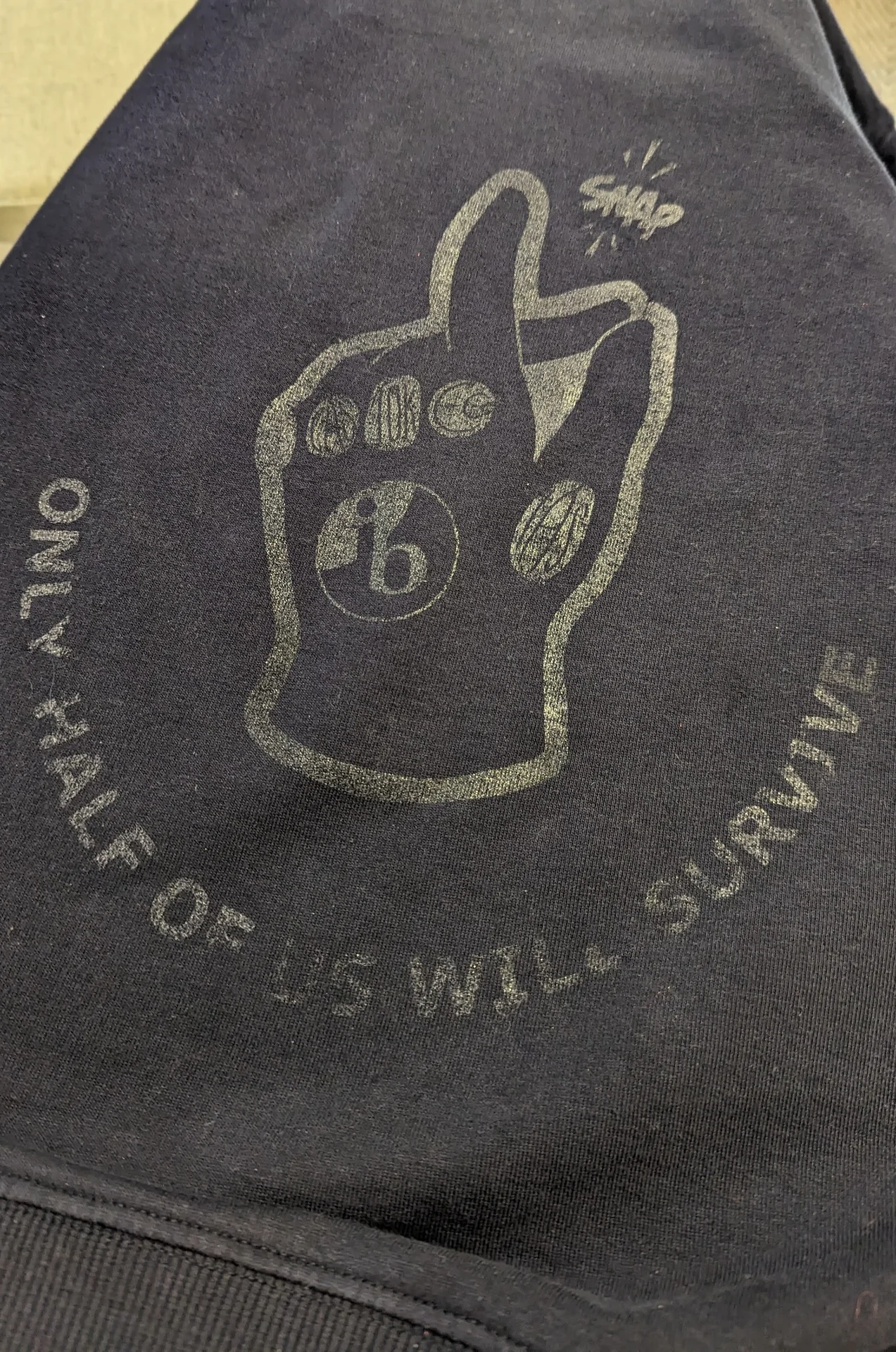
In Finland, there is a tradition in many high schools to print custom hoodies for third-year students usually featuring the school’s logo and a custom design made by the students. Below is mine for reference, with an overly large logo in the front as a result of a printing mistake and our IB classes design on the back, the credit of which goes to Viivi Kankaanpää and Rosa Linke with me witnessing and participating in the conversation.
Rosa, however, experienced buyer’s remorse about having ordered a yellow one instead of dark blue. The hoodies had obviously long since become unavailable as only a single batch was ever made and we are already deep into our second years in our respective universities, but I thought that this would be a great opportunity for purchasing a unicolor, dark blue hoodie and heat pressing the vinyl-cut logos on it to create one more in her desired color.
Preparation
I got the original custom design from Viivi in .png form and found a variant of our old high school’s old logo from Google image search, also as a .png. I sent an email to Tampereen lyseon lukio’s current principle and she authorized me to use and modify the logo for this purpose within 6 minutes of sending it.
I donwloaded the only available logo variant and opened it in Inkscape. I then used its “Trace Bitmap” functionality to convert the clean black-and-white png to a vector graphic, which worked flawlessly.
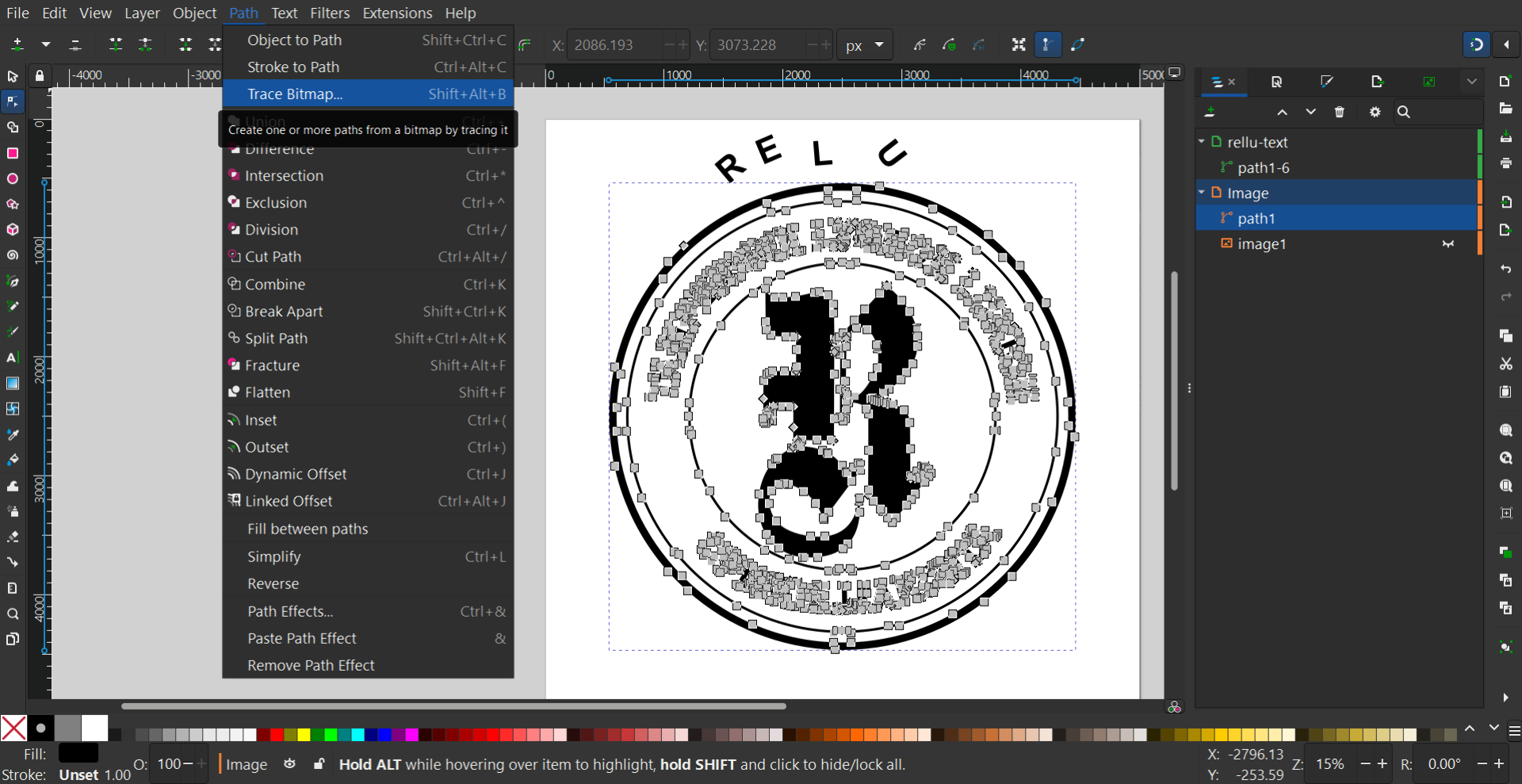
I then selected and removed the text and replaced them with my own using the Times New Roman font by drawing two circles and using “Text > Put on Path” to make the text follow them. I centered the text between the circles by adjusting the radii of the invisible helper circles I made and adjusted the font sizes and letter spacing to 250 and 30 respectively, producing the SVG embedded below, but without the text. Exporting it as “Plain SVG” lost the text for some reason and after a while of searching why this would be, I chose to take the simplest route of simply selecting “Path –> Object to Path” and re-exporting it. I copy-pasted the contents of the rellu-logo-tnr-optimized.svg file below here in the markdown and set its width and height to 100% to adapt to container size and fill to var(--pre-text-color) to automatically adapt to the theme of the site.
Below is our IB classes custom graphic inspired by Avengers: Infinity War. It refers to “The Snap”, with which Thanos erased half of the population of the Marvel Cinematic Universe after having collected all six infinity stones to power his infinity gauntlet, and so plays on the relatively high IB dropout rates. For some reason, “Trace Bitmap” did not work on the white .png file, even after applying a black color filter to it from “Filter -> Color -> Colorize”. The most straightforward way was then to just save this as a black .png, open it in a new project and then use “Trace Bitmap”, which worked just as expected.
The markdown file with hundreds of lines of numbers between the <svg> tags looks pretty horrendous but they look great on the site!
It seems I had accidentally set Google Chrome as the default app to open .svg files and right-clicking in File Explorer caused it to crash… Not being willing to wait for a restart, I googled “svg viewer” and found svgviewer.dev, which is a neat website for viewing .svg files by just dragging and dropping them in. It also works as a hub for uploading, viewing and downloading community-generated SVGs and allows you to edit and optimize them as well as convert them into React components, PNG files or Data URIs. I used it to optimize and copy the code for the above SVGs.
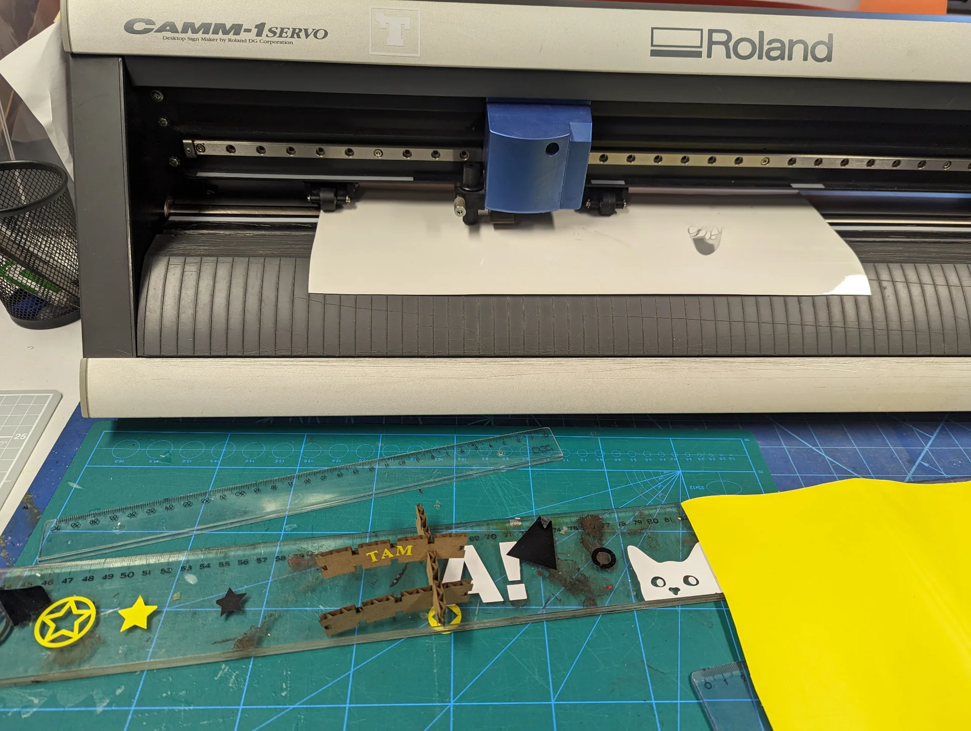
Using Roland GX-24
For vinyl cutting, Aalto Fablab had the Roland GX-24 vinyl cutter, documentation for the usage of which can be found here on Aalto wiki. I got a quick tutorial from Burak Türköz who with Saskia Helinska were incredibly helpful with the execution part of this week’s assignment.
On paper, the process is rather simple. As detailed in Aalto Wiki: turn on the machine, raise the rollers by pressing down the loading lever, insert material of 50 to 700 millimeters in width such that it covers the light sensor and adjust the pinch rollers from the back so that they are just outside the edges of the cutting area but such that they are under the white marks and lower them by lifting up the lever. Then, select the mode for loading the material based on its lenght and press enter. In my case, this was “Piece” for loading a small amount of material from the front.
!!! VERY IMPORTANT TIPS FOR LOADING THE MATERIAL !!!
Make sure you know what you are doing with the materials. Ask people in the lab if you don’t or make sure to carefully read someone else’s documentation who has done something similar. In the above picture, there are a total of three things wrong, even though they cannot be seen. First, the heat transfer vinyl is shiny side up, even though it should be the other way around to cut the correct side. From this side, the material was not properly cut and could not be successfully weeded. Even if it would have, heat pressing would likely not have worked. Second, the logo was not mirrored over the vertical axis, even though it should have when cutting the heat transfer vinyl the right way around. Third, most importantly, the piece of material was not large enough and the logo got cut off at the top. The rollers are what move the material back and forth and the blade is a bit in front of them. That means that there must be enough excess material above the area to be cut so that the rollers can roll it far enough to cut the entire length. The cutting area is shown in the display after setup, so do make sure that it is greater than whatever is to be cut.
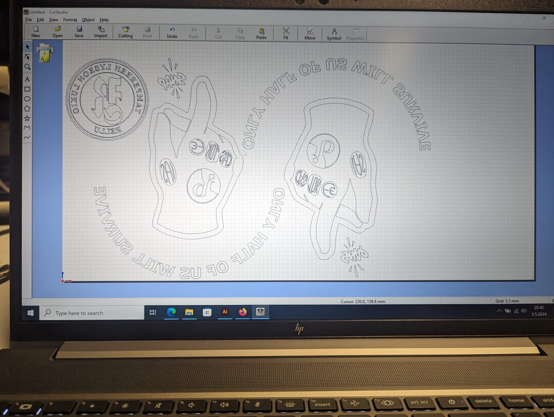
On the computer sitting next to the machine, the workflow was theoretically very straightforward. Simply open up the vector file to be printed in Adobe Illustrator, adjust it to be the correct size if necessary, make sure the shapes are closed and filled with color and send it to Roland CutStudio via “Window > Extensions > Roland CutStudio”. However, Illustrator had apparently been updated the day before I got there and CutStudio had dissappeared from the menu due to not having yet been updated. Luckily Krisjanis Rijnieks, our “Fablab Master” luckily came up with the following workaround: go to “File > Save as > Save on your computer”, choose “Format: Illustrator EPS” and choose “Version: Illustrator 3 EPS”. This can them be imported to CutStudio by just clicking “Import” and selecting the correct file, which is then loaded to the application as shown below. The next day, I noticed a coursemate sitting in the same chair looking frustrated and so I got to quickly pass on my knowledge, which then worked for him too.
![]()
In the picture, I mirrored the Tampereen Lyseon Lukio vector logo by selecting “Object > Mirror”, so that it would be the correct way around for heat pressing as that requires cutting the other side of the material. This, as I already mentioned, I also first did wrong, wasting the only white piece of scrap material, forcing me to use another color for the final test.
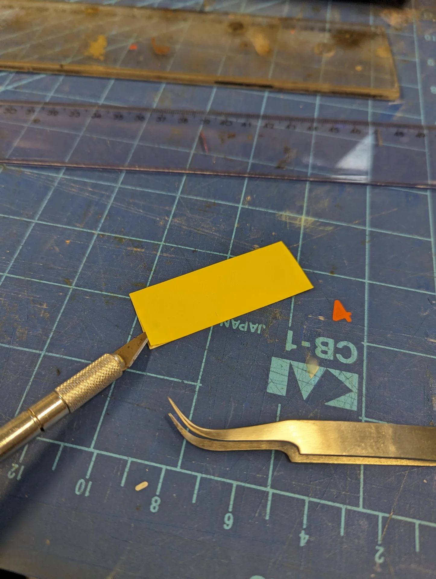
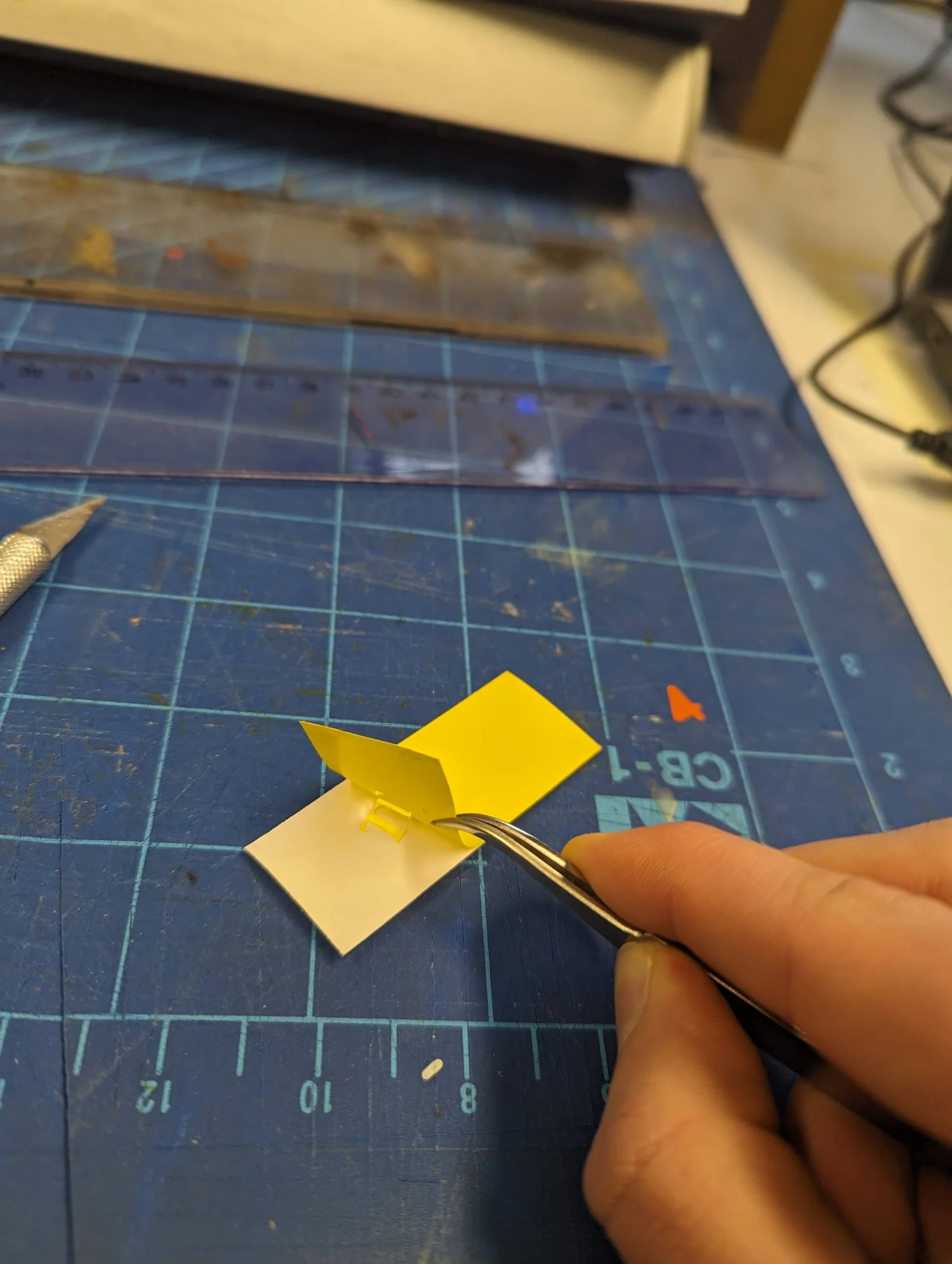
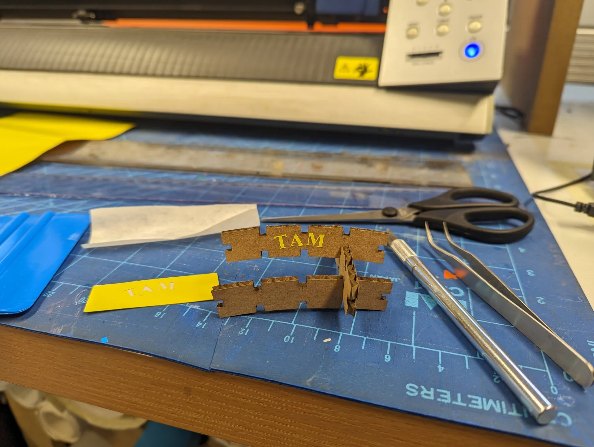
Before that, however, I wanted to make sure that the small and thin Times New Roman letters would be properly cut. I experimentally cut a few of what I thought to be the most difficult letters (this eventually turned out to be “E”) by importing them to CutStudio and pressing “Cutting”, ensuring Roland GX-24 is selected and pressing “OK”, in order to see if the cut was accurate enough and if I could peel off the excess vinyl. This weeding process turned out to be very delicate, especially with the weak adhesive between the back and front sides of the material. I did, however, succeed to peel of the excess - even though “A” moved around a little - and to stick it to my laser-cut prototype pieces using transfer tape as shown below
Luckily, the adhesive in the heat transfer vinyl was a lot stronger, so that the weeding process was a lot easier and faster. After having failed with the cutting of the white scrap piece, I made sure to pick a large enough next, place it the right way and to mirror the logo. This resulted in the following:
Heat pressing
The hoodie was ordered soon after and when it finally arrived and I got a bit of time, we went down to the lab with Rosa to cut both the smaller Rellu logo as well as the larger custom graphic of our IB class and heat press them onto it. I loaded some scrap material to work out the margins necessary, which turned out to be approximately 6cm for length and 5cm for width. As we wanted the larger graphic to have a height of approximately 27-28cm similarly to my hoodie, I cut 35cm of the near 50cm wide roll, which gave us the dimensions of 453mm of width and 291mm of length to work with. I resized the vectors in Illustrator and imported the Illustrator EPS 3 files into Roland CutStudio, mirrored them and placed them so that should something go wrong, I would still have space to cut it again as shown below. Luckily this was not necessary and I only cut the two leftmost logos.
![]()
![]()
The heat press in Aalto FabLab is The MAXX® Clam Heat Press by Stahls’, the operation of which is relatively simple:
- Plug it in to a wall outlet or a maximally short heavy duty extension cord.
- Power it on from the power switch on the right side of the control panel.
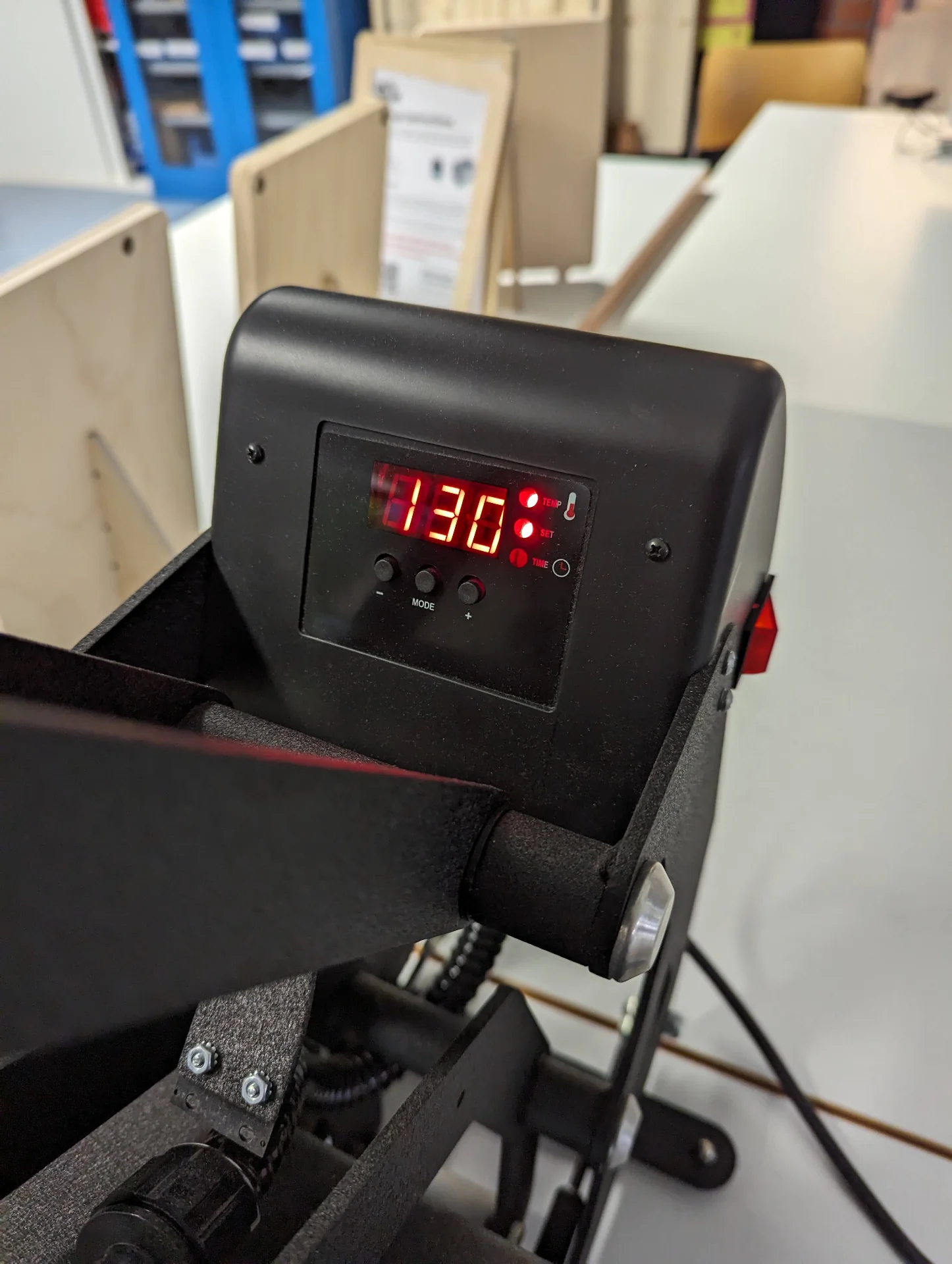
- Press “MODE” once to set the target temperature in celsius using “+” or “-”.
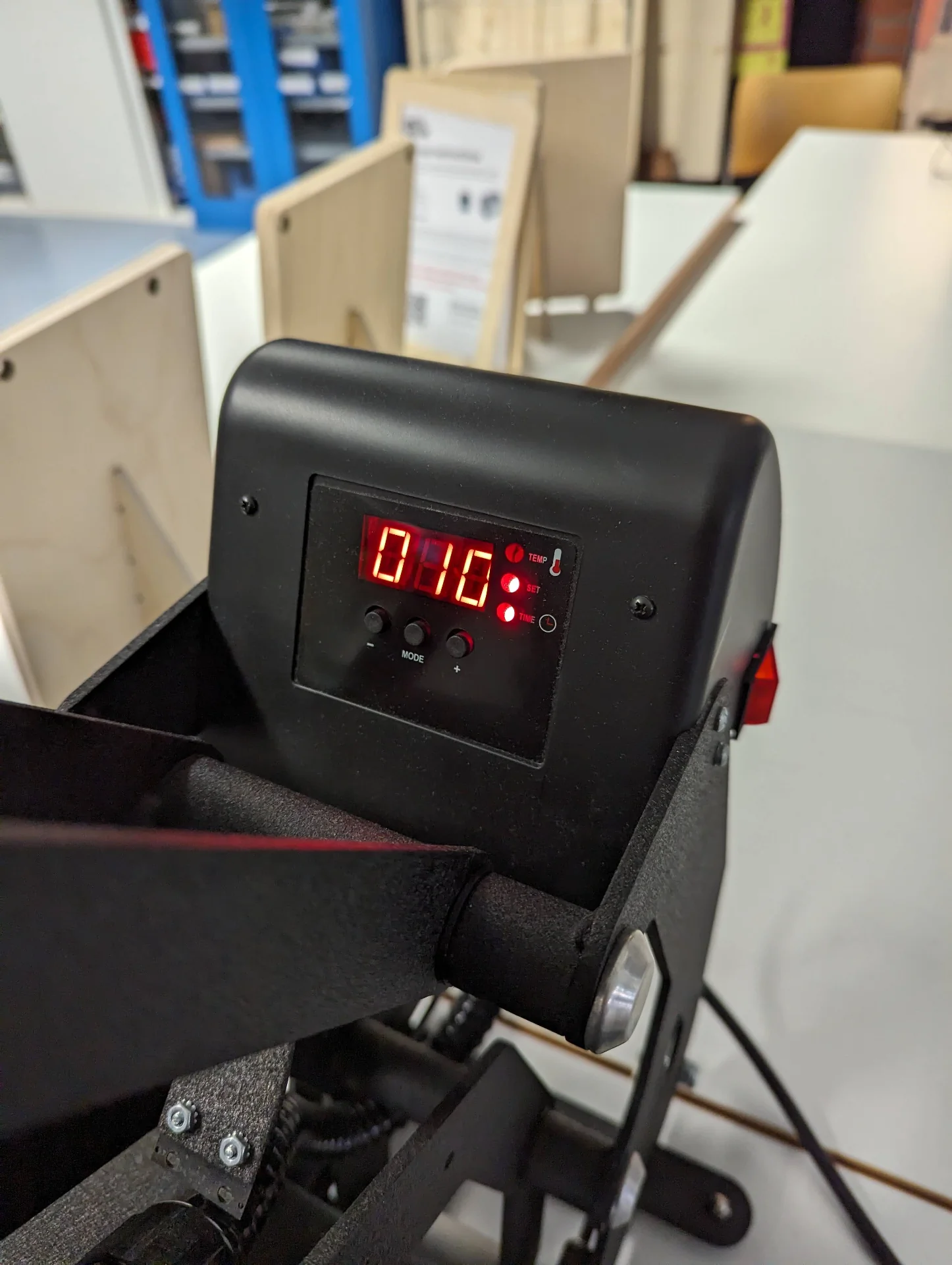
- Press “MODE” again to set the time in seconds using “+” or “-”.
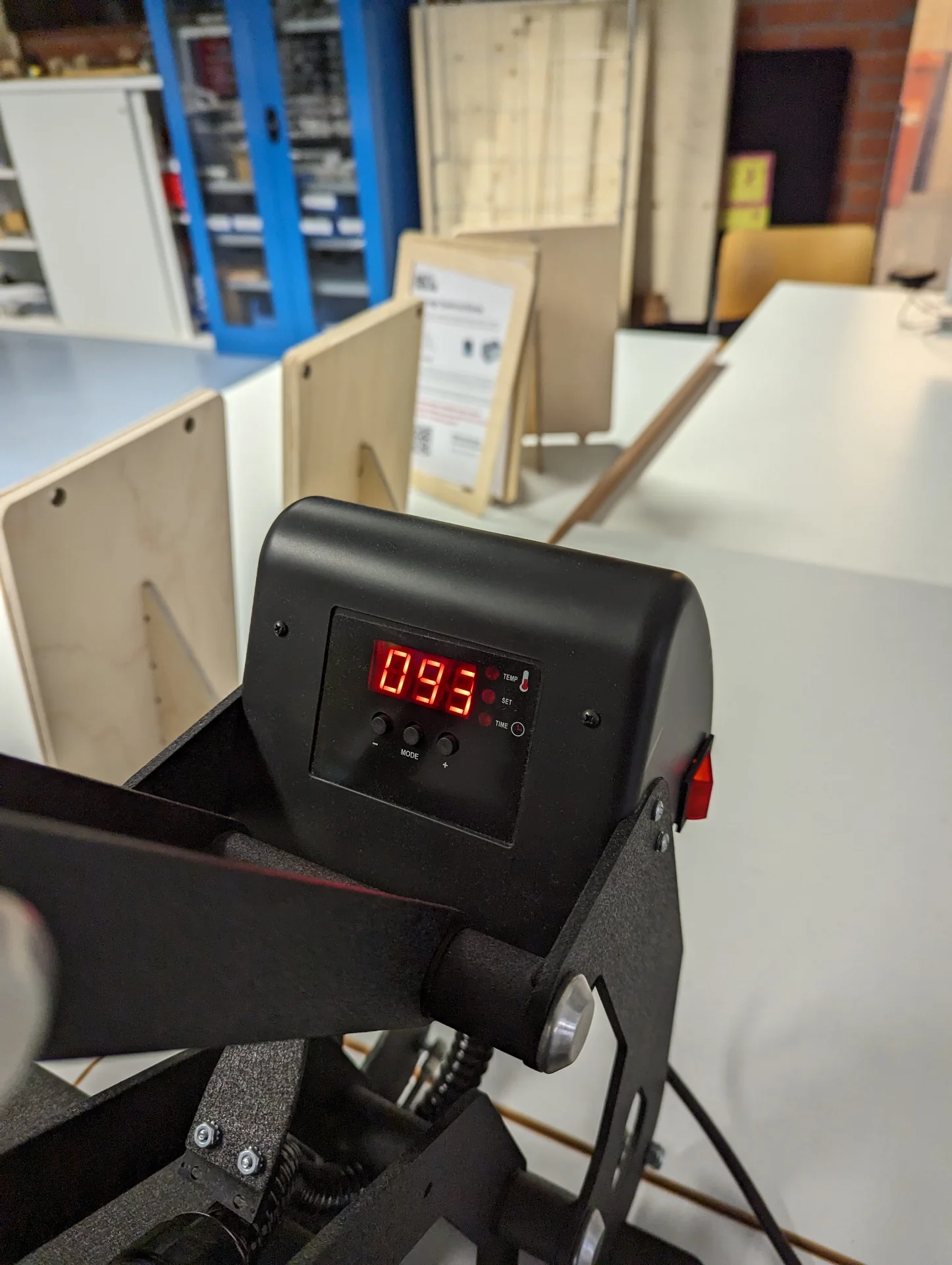
- Press “MODE” again to view the current temperature, which only shows readings above 93°C.
- Wait until the target temperature is reached.
- Set fabric or clothing item on the platform and align the heat transfer vinyl (HTV).
- Cover both the heat transfer vinyl and the fabric with baking paper or similar to prevent damage to the vinyl.
- Push down the clamp so that it gets locked down and the clock countdown starts.
- Wait until the time has passed and lift up the clamp.
- Turn off the heat press and disconnect it from the outlet.
- Remove the vinyl backside and witness the vinyl sticking to the fabric.
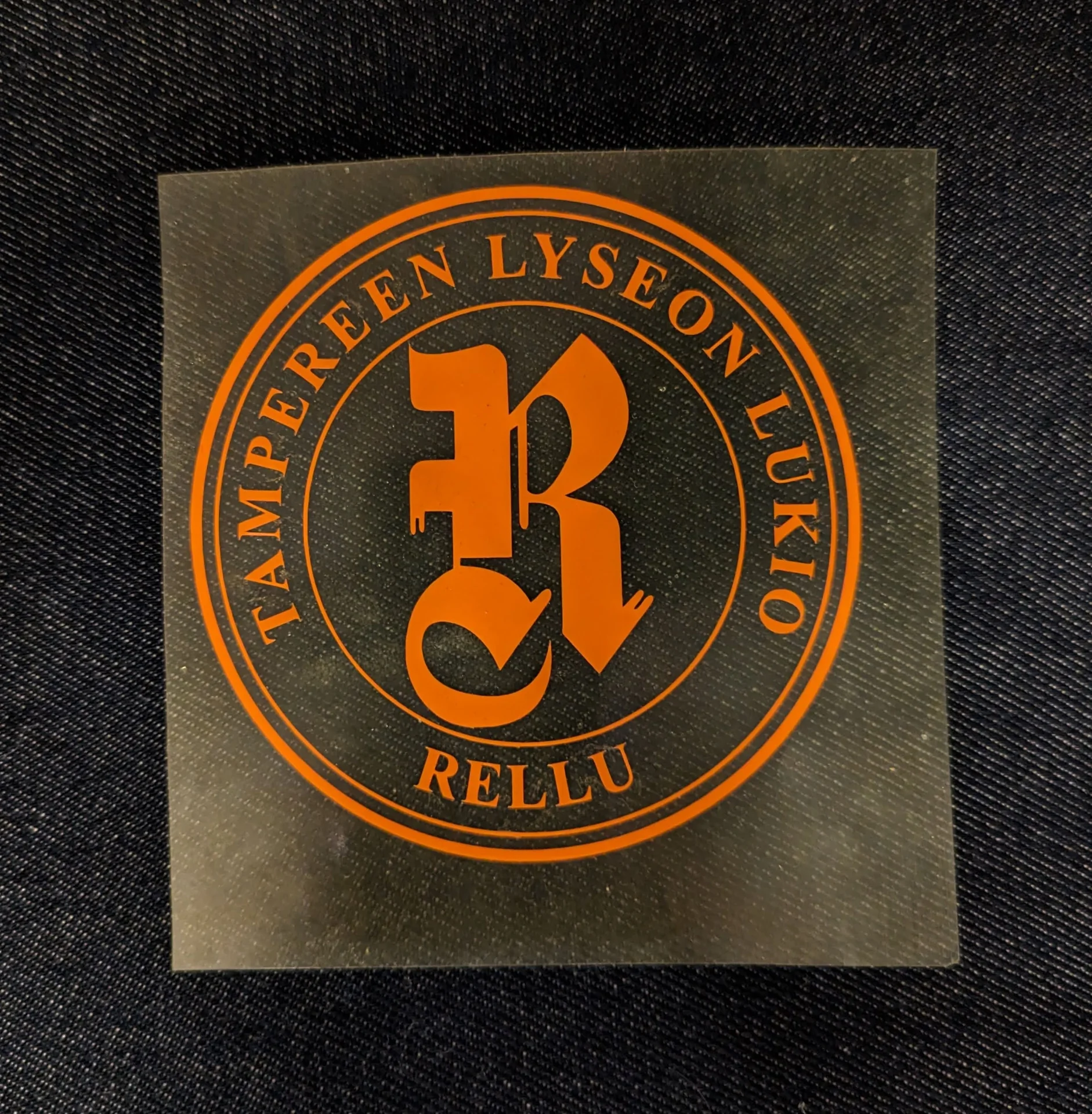
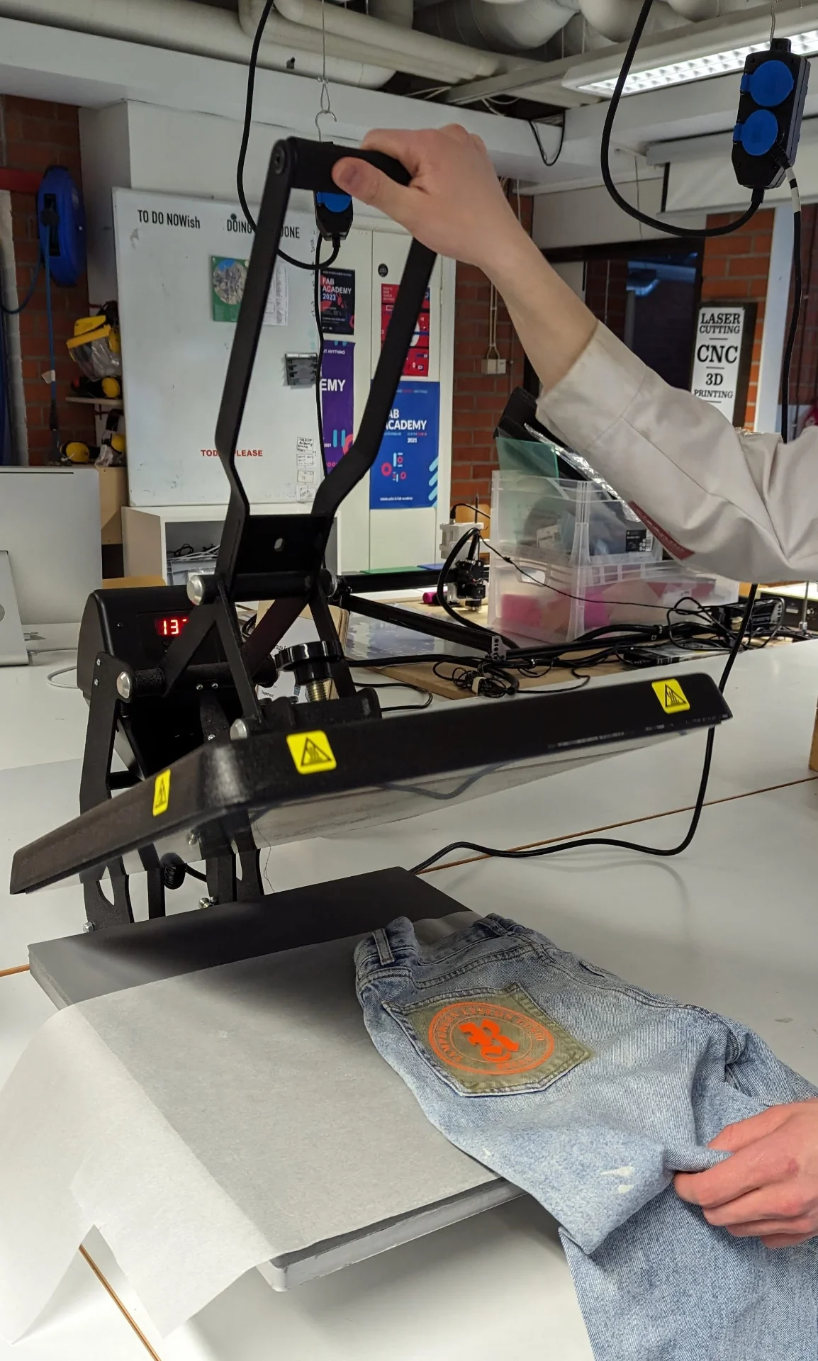
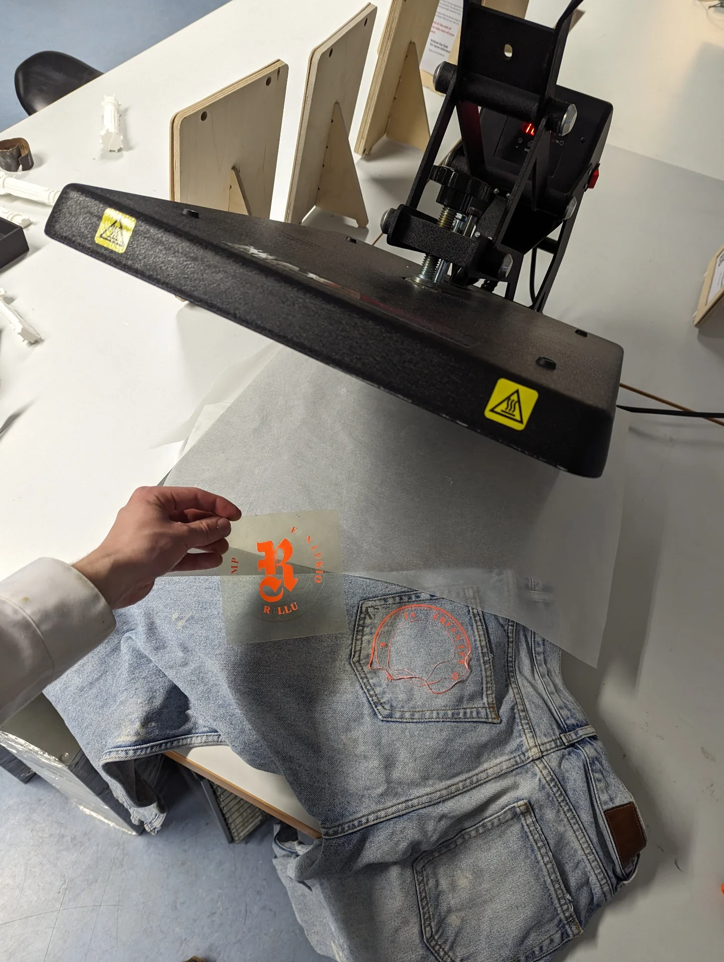
We did a trial run with the orange logo on old dirty jeans that are no longer used, but this turned out to be a miserable failure as seen below. This is likely due to a multitude of reasons having to do with incorrect placement of a difficult fabric and incorrect use of the heat press. We were not certain about the material, the jeans had lots of thick seams, we had the baking paper on the wrong side and I failed to press it down fully so that there was not enough pressure. As a result, only some of the vinyl stuck.
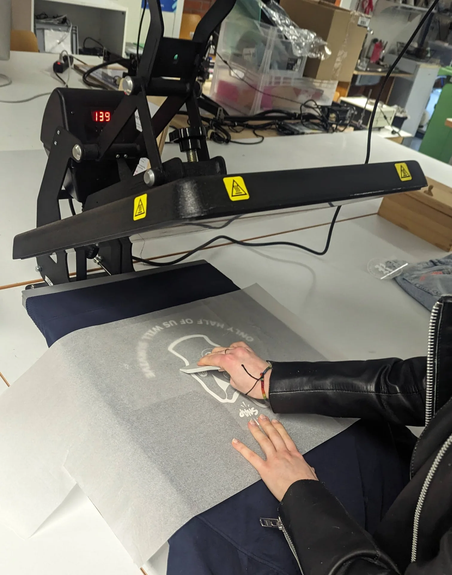
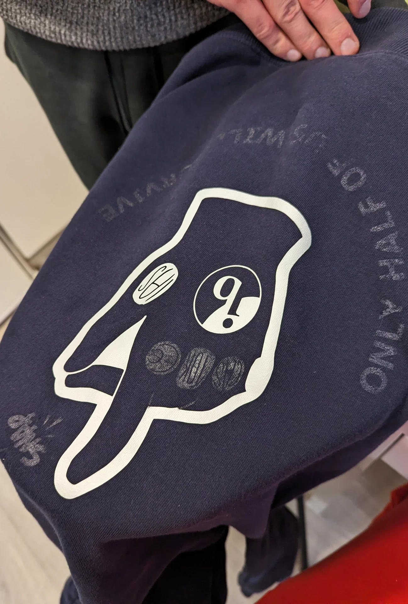
We decided to take these lessons and proceed to the hoodie. This time we made sure to be very careful about how we positioned it in the clamp. We essentially made the lower one wear it so that only the backside is exposed. We then pre-heated it the fabric by pressing it down for around 15 seconds. We then put the baking paper on top and pressed the vinyl’s adhesive side meticulously on the hoodie. Now that we also knew exactly the material we could set the temperature and time accordingly. The STAHLS SPORTSFILM WHITE 001 material was to be pressed in 130°C to 150°C for 10 or 5 seconds depending on the temperature. As we had observed that no meaningful damage had occurred to either the jeans nor the vinyl in the previous pressing, we decided to play it safe and press it for 15 seconds at 140°C so that it would certainly stick properly.
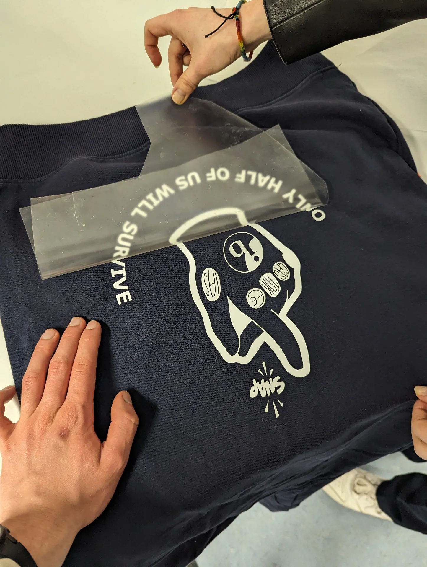
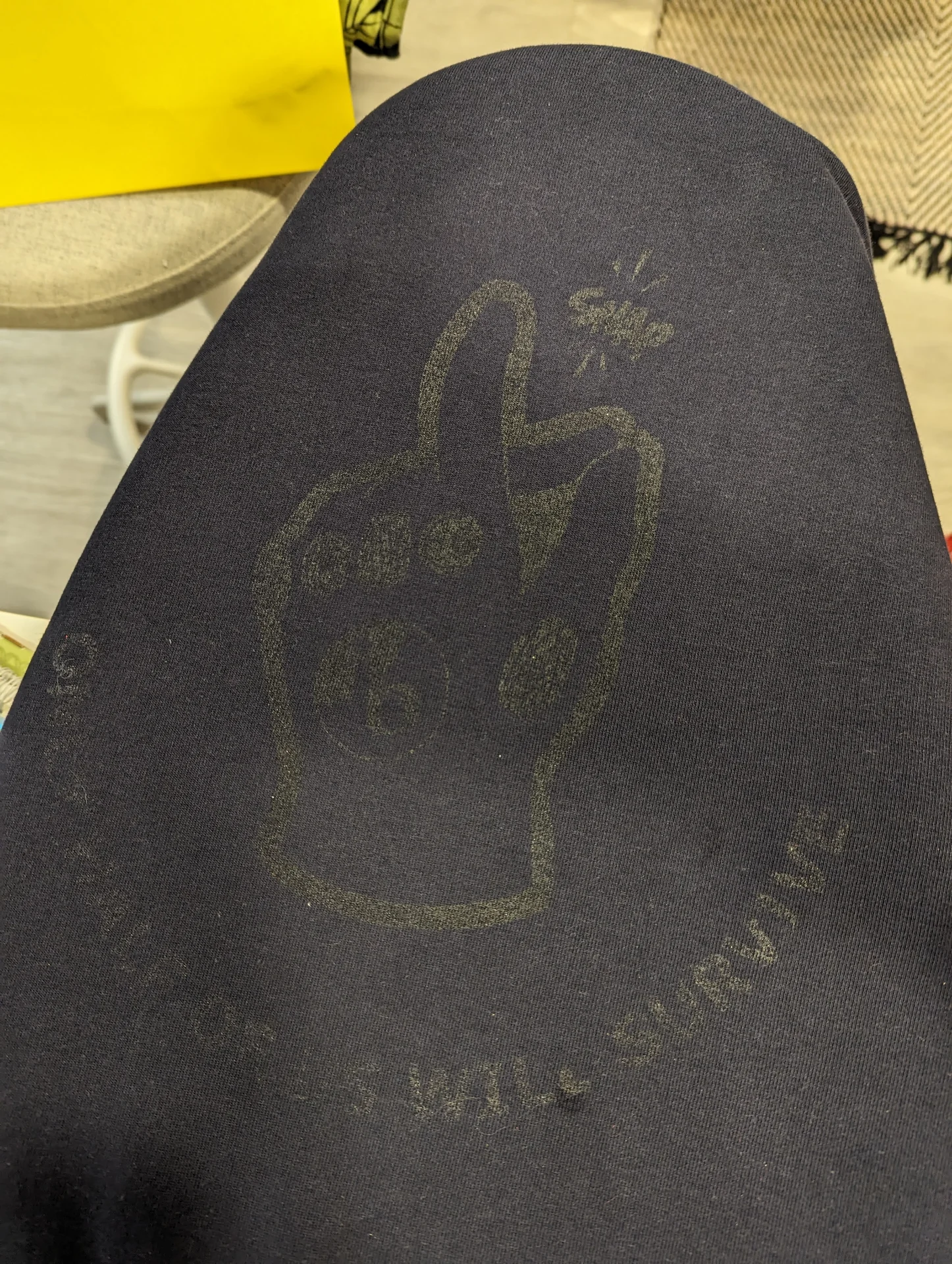
Below are the results of the successful heat pressing. As can be seen, however, both of the graphics unfortunately ended up being quite low, but it is still usable and the process overall was successful.
Not being quite satisfied, we decided to take a risk with trying to remove the vinyl and heat pressing them again on the same hoodie so that it would either look like an original or at least we would learn a lot more. I researched how to do this and discovered this blog post on the topic, which instructed us to heat the fabric up to the same temperature used for applying the vinyl, using tweezers to rip the the vinyl off and then getting rid of the glue residues using heated paper.
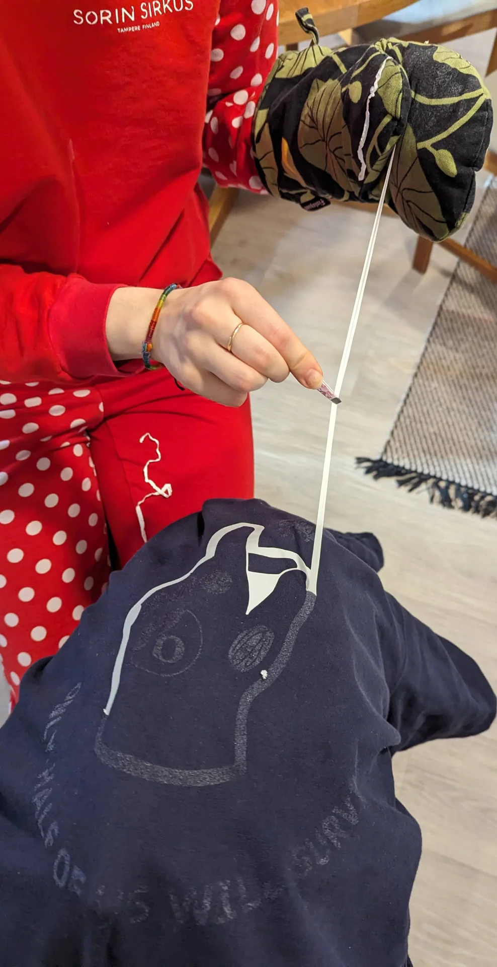

As we tried to do the removal process at home, we had to use a clothing iron but it did not have explicit temperature settings, only a spectrum from low to high temperature for different kinds of fabrics. In order to figure out which setting to use, I consulted a table in the Wikipedia article for “ironing”, which implied that 140°C should be around 2 stars, but as the hoodie was cotton, we decided to position the switch between 2 and 3 stars, eventually sliding it upwards for increased efficacy.
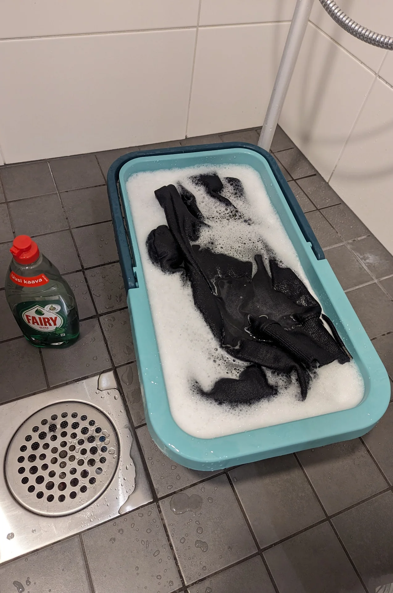
We placed the iron on the other side of the fabric, under the area from which the vinyl were to be removed and pulled the fabric taut. We waited for a while and soon began removing the vinyl. Eventually I became quite quick at this by sticking the sharpest corner of the tweezers under the largest continuous area of the vinyl currently being removed and pulling steadily. This left some glue residues but according to the blog post, these could be gotten rid of using copy paper, which we tried by covering the stains with a paper and heating it up with the clothing iron for around a minute or so. After pulling away the paper and repeating this a couple of times, we managed to get rid of most of it so that it was only more visible at certain angles anymore. To try to get rid of it fully, we left it overnight in hot water with a lot of fairy.
Laser cutting
Safety and documentation
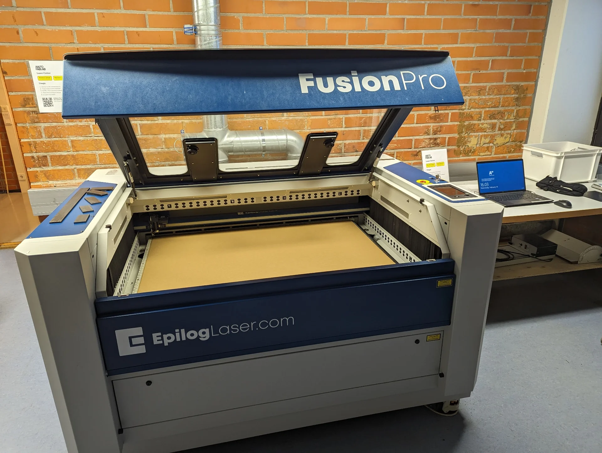
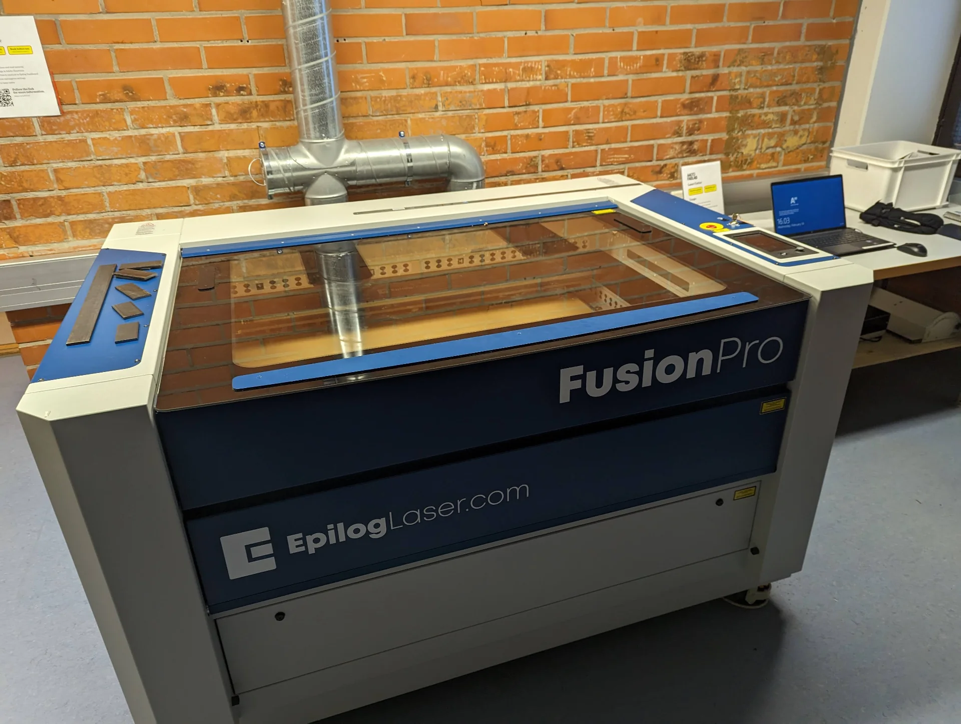
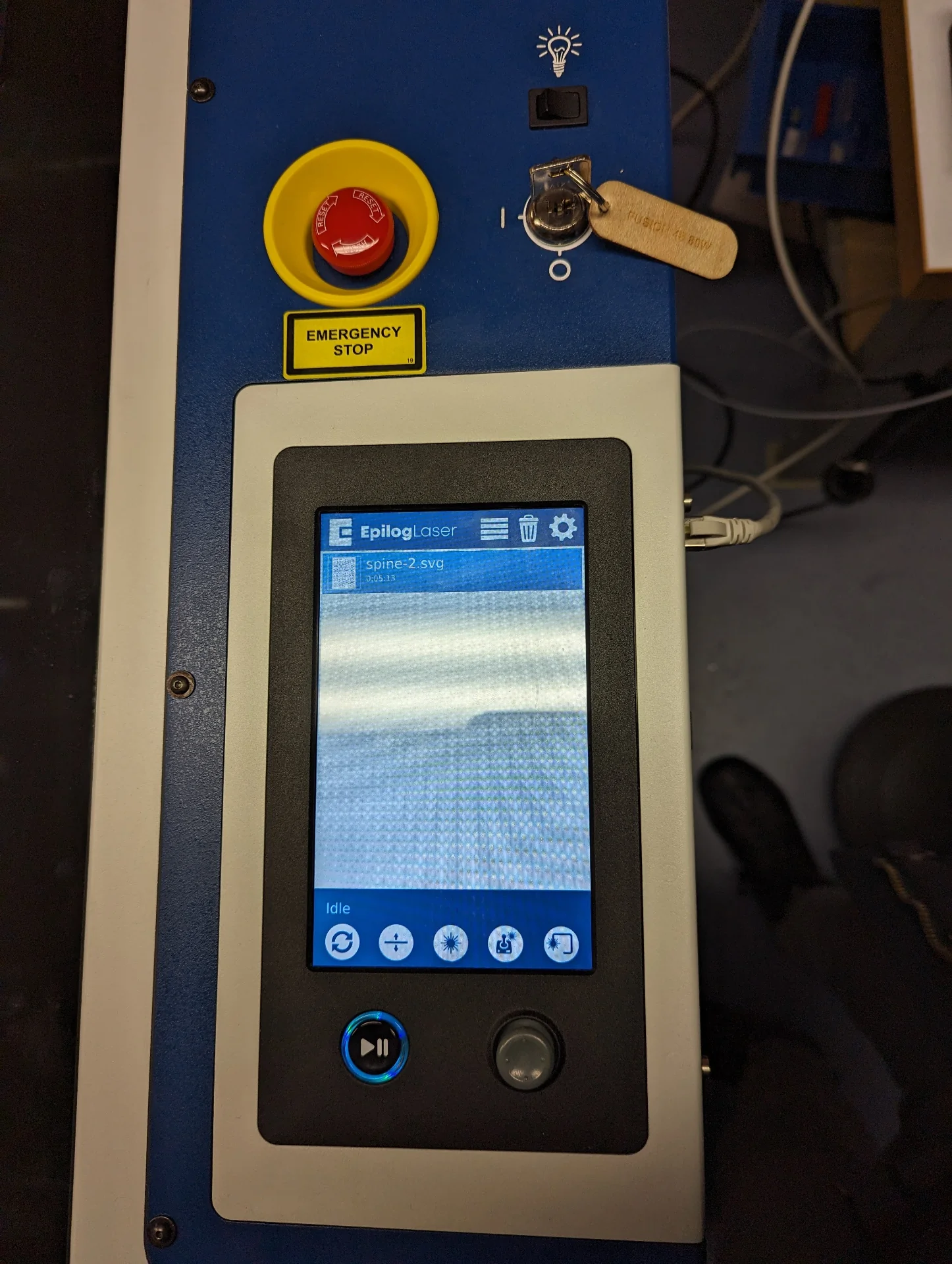
Graham Featherstone was appointed our group leader / secretary and thus wrote our group’s this week’s documentation on the use of the Epilog Fusion Pro 48 laser cutter, which can be found here. Aalto Fablab also has extensive step-by-step documentation about its everyday use on the Aalto University Wiki.
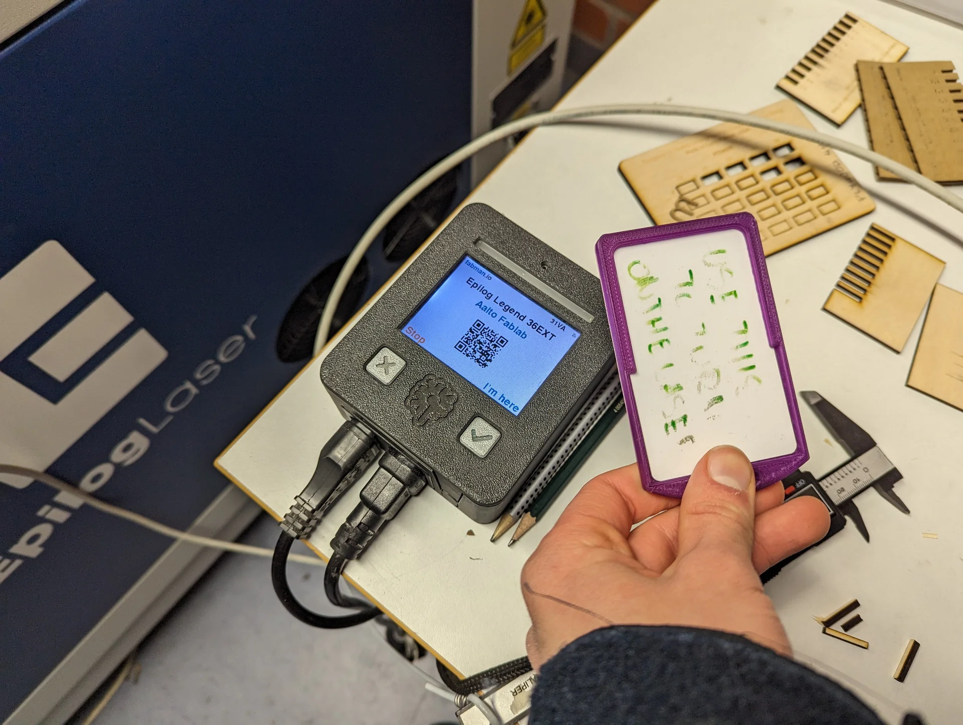
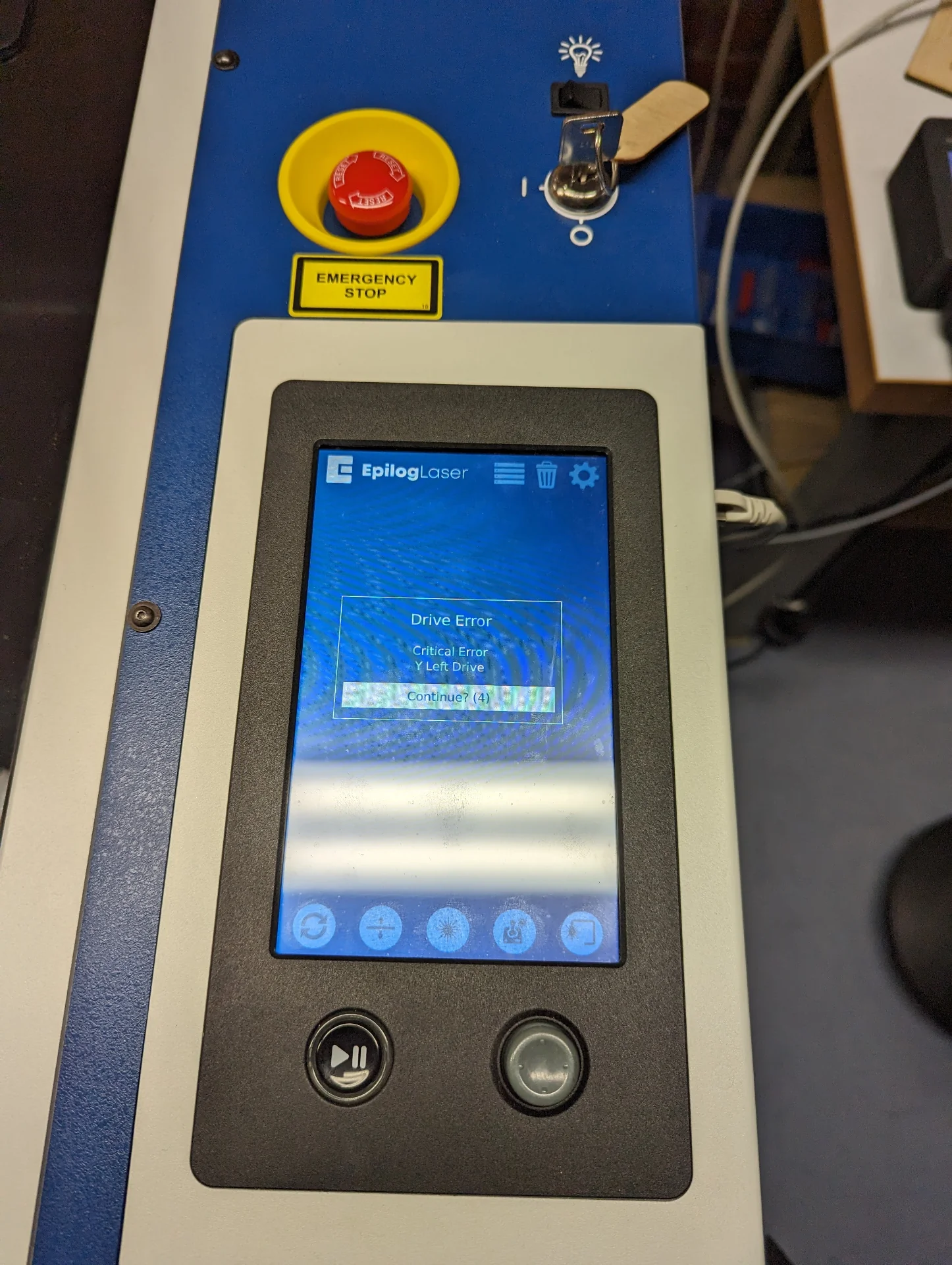
To briefly summarize the process: turn on ventilation to the max, register your presence (periodically every 5 minutes) by tapping the card reader with the card next to it, open the laser cutter lid, insert your material and close the lid, turn the key (available during 9 - 16 from staff) to turn on the laser cutter, open designs in Illustrator, choose “File > Print”, position them in the Epilog software, adjust speed and power, set “Auto Focus” to “Plunger”, click “Print” on the computer and then press the play/pause button on the machine after which, enjoy the satisfying show. When finished, wait a moment for the air to clear out inside the machine before opening the lid. In case of small trouble, press the play/pause button on the machine to pause the cutting. In case of big trouble, press the big red button. In case of software issues, turning it off and on again seems to work here too.
Video was lazily cut with Clipchamp, compressed with the first online compressor resulting from the google search “compress mp4” because Clipchamp does not seem to have any export settings on a fast glimpse and embedded with the following shortcode, where “loop” and “muted” unfortunately do not seem to be doing anything:
|
|
Project ideation
Such wonderful opportunities as this course bring with them a sense of pressure to create cool, inspiring and preferably useful projects and thus the ideation phase is always the toughest. This was made even more so by the free material of choice being cardboard, which is not exactly the strongest, most durable and stable material out there. I thought about creating some kind of stationary holders or organizers but these might have fallen into the “boxes with finger joints” category a bit too easily. Other ideas included a bed-mountable stand for our portable projector but instead of trying to engineer structurally sound cardboard structures, I then turned to the domain of decoration. I wanted it to be something that would be easy to integrate into our apartment. Others have made, for example, lamp shades but we had no need for such currently.
I then got the idea that skeletons would probably be quite well suited for a parametric press-fit construction kit as they often appear modular and always have pieces of bone jutting out anyway. Furthermore, I was always absolutely fascinated with dinosaurs and dragons as a kid. I therefore got the idea for the dragon construction kit, as it could be easily integrated into the environment, would look somewhat natural and was just a cool idea. Below is a bit of a spoilery sneak peek into what I was thinking and how the dragons could be created around objects.
3D modeling
This time I chose to go with Fusion 360 as I needed more reliablility and a more robust assembly feature with better documentation than what Ondsel currently has. It was not without its issues either as at one point I got a weird glitch, in which everything to the negative Y-direction got clipped at an arbitrary point such that if I tried to rotate a component, any part beyond the Y-plane just dissappeared. I wrestled with this a bit but eventually a simple restart fixed the issue, further permeating the old wisdom of always trying a restart first.
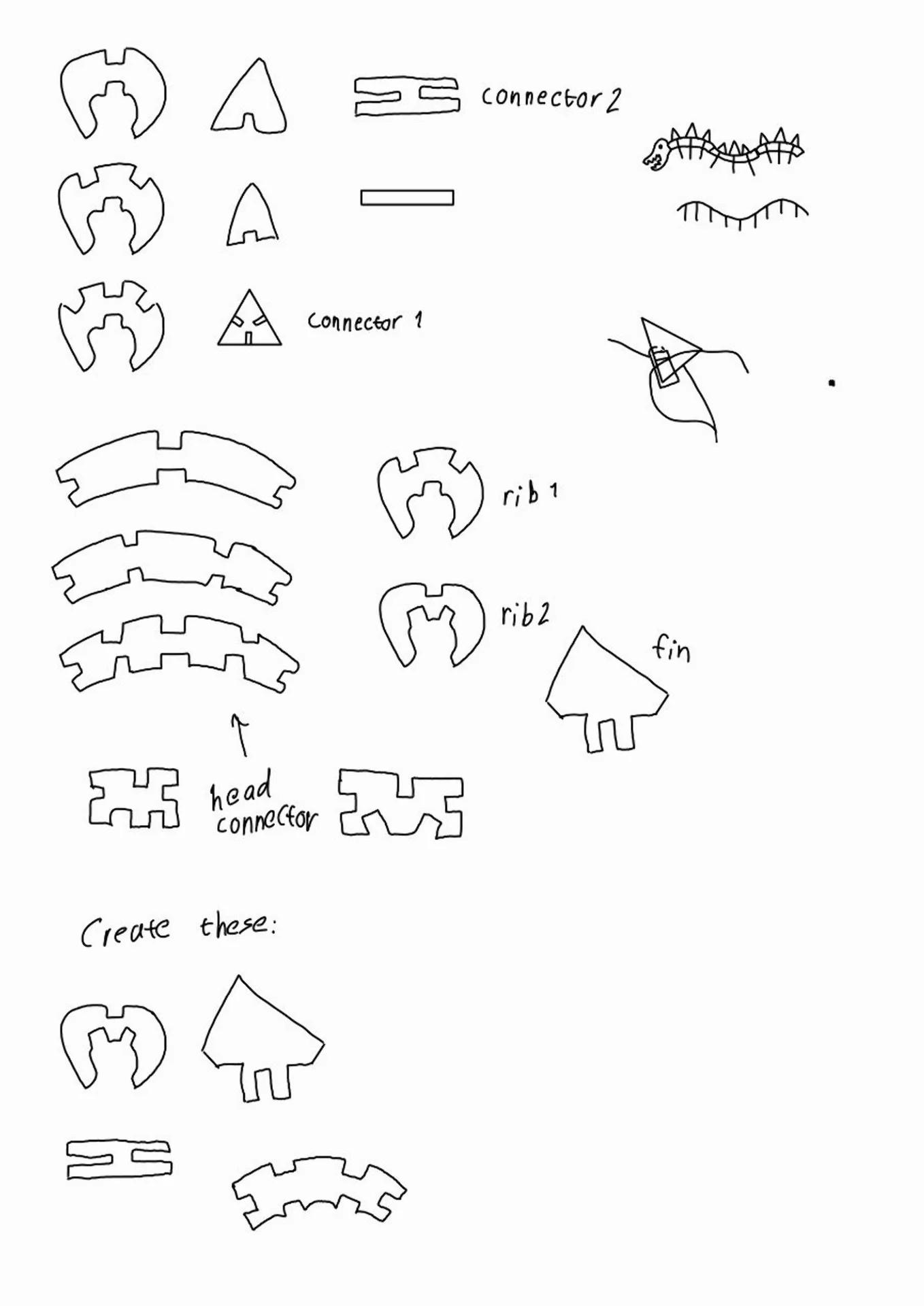
Quite a significant portion of the modeling and assembly occured entirely in my head. I spent an evening envisioning and assembling the minimal set of components required to build what I wanted to create in my head, drawing the following sketches as a byproduct:
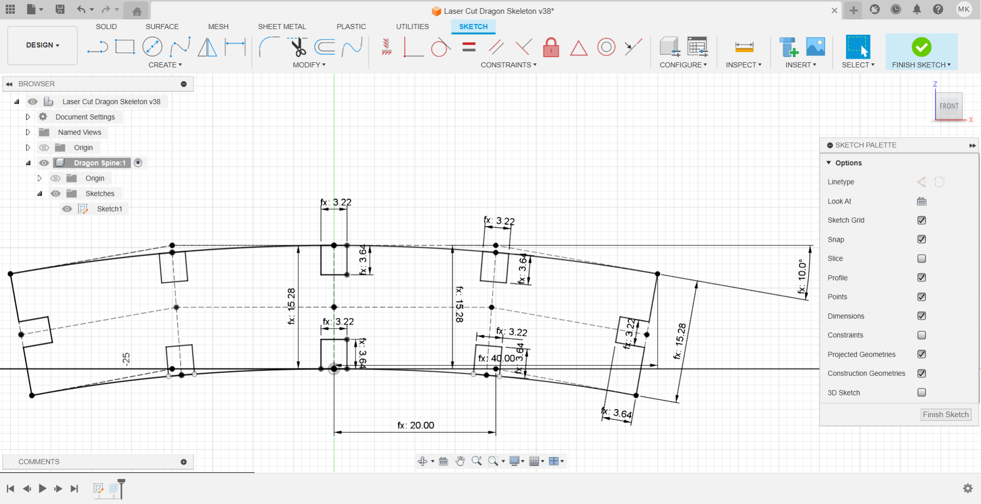
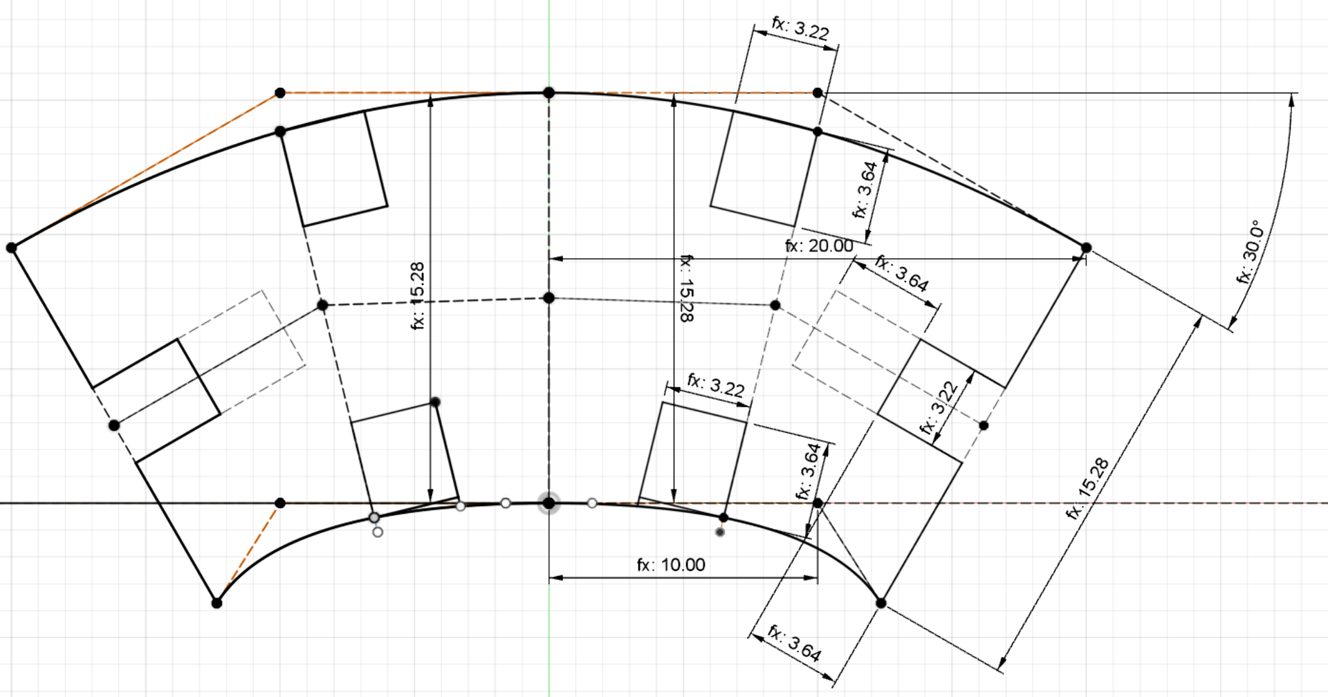
I then opened Fusion 360 and sketched my first dragon spine component as follows. To make it truly parametric, I researched and found that in Fusion 360, the parameters are accessed via “Modify > Change Parameters” and they appear to be global, unlike in Ondsel/FreeCAD where one can simply point to whichever spreadsheet file, which to me is actually more intuitive.
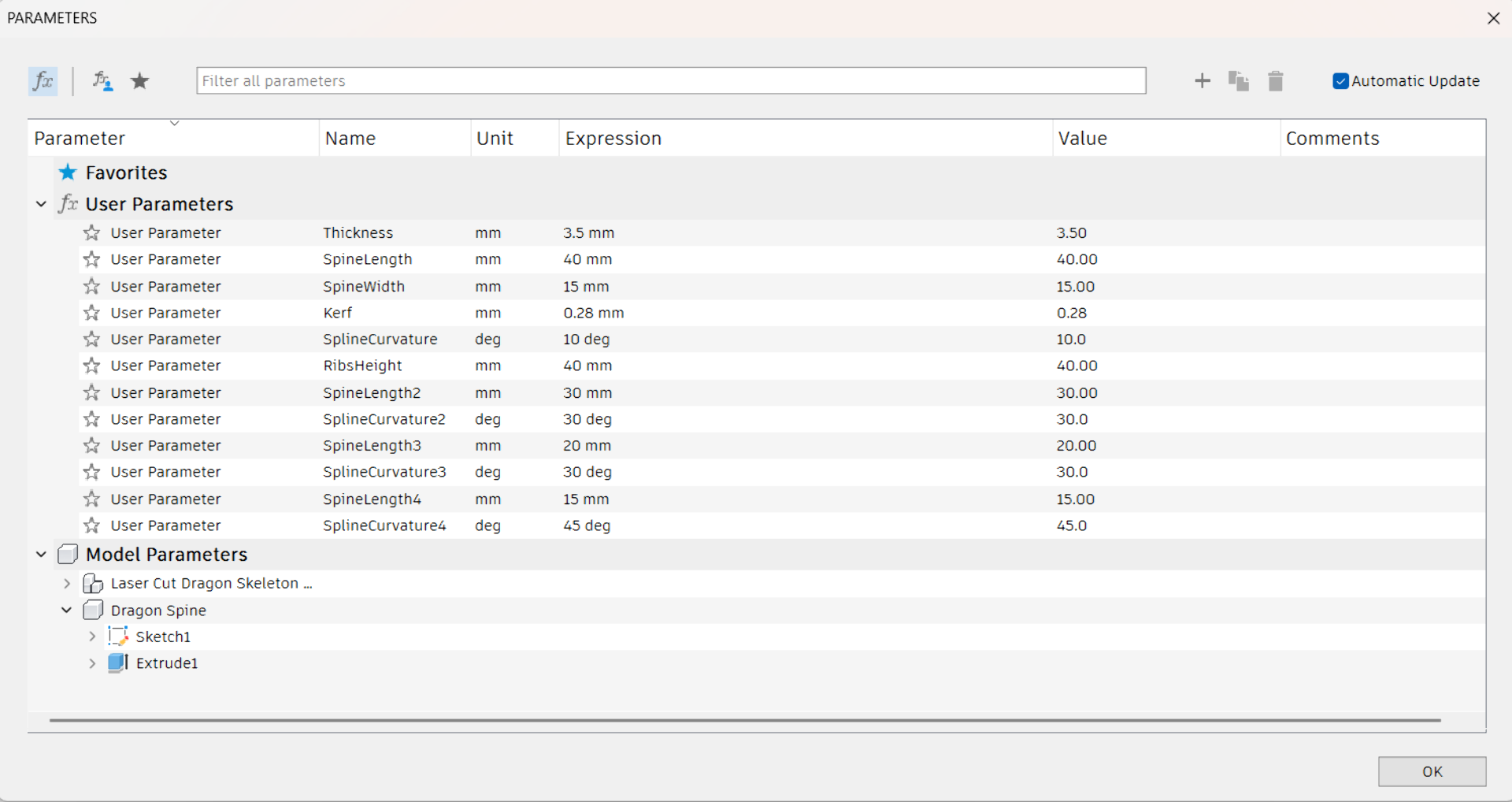
Below are also the final global parameters used for the kit. By Krisjanis’ recommendation, I added the Kerf (width of the cut produced by the laser) to the parameters and defined all dimensions of the sketch with functions that either added (for outer edges) or reduced (inner edges) either half or the entire kerf value, depending on whether the distance measured concerned inner or outer edges and whether the distance touched two edges or only one. In the demo session, the kerf was measured to be 0.28mm and the thickness of the cardboard as 3.5mm. The width of the spine was chosen to be 15mm to enable the full use of two opposing joints, which would take 4 * 3.5mm = 14mm. I now also notice that everywhere else I dealt with the kerf correctly, except that in the depths of joints, I accidentally added it instead of subtracting it but this one could characterize as a happy accident as it only produces an ever so slightly tighter fit and it still fits within that 15mm safe margin. The length and curvature, on the other hand, were initially entirely made up.
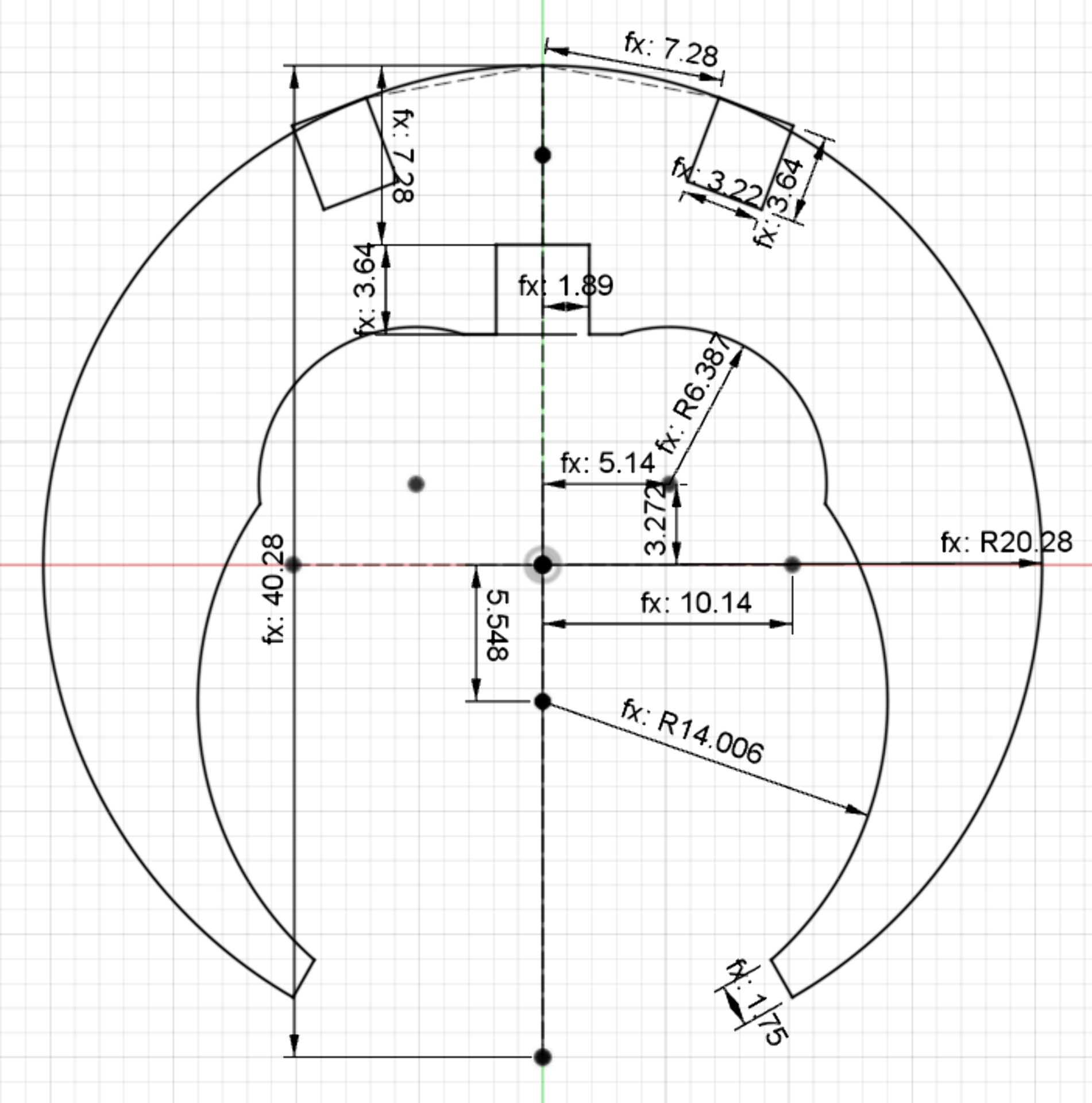
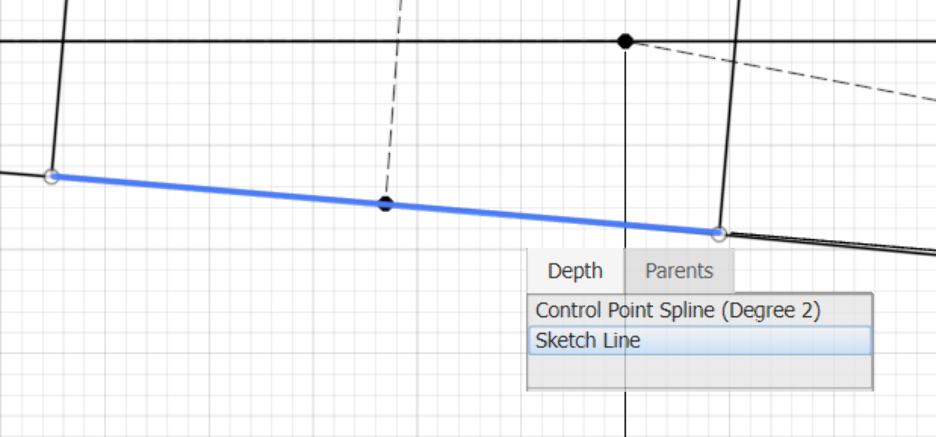
Here the mirror function was key part in the design of all components, where I only ever drew and constrained half a sketch and then mirrored it about the Z-axis. Another essential tip is to long-press left-click on top of lines and points in the sketch to bring about a context menu that shows all stacked drawings and allows for the selection of any of the layers. This was often the fastest way to find missing constraints and other sources of unexpected behavior. It is also a good idea to get acquainted with the shortcuts to significantly speed up the workflow.
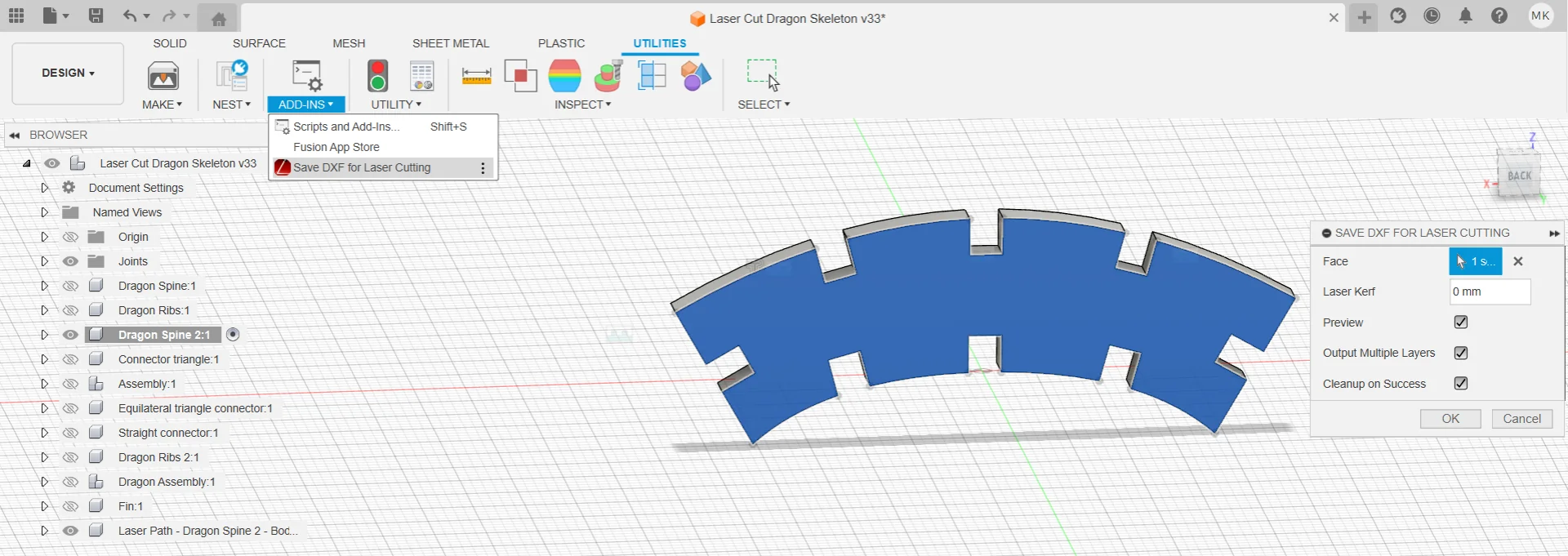
Along with the spine, I also modeled the ribs component, with which I then went to the lab on Monday to experiment with how well they would fit together. In order to prepare the necessary vector files for cutting, I downloaded and installed the DXF for Laser add-in for Fusion 360, with which I could create the cutting instructions compatible with the laser cutter. I was initially surprised that it did not work quite as I expected. One cannot select a sketch and export that. Instead, you have to be in the 3D view, select a face of the object and then save it as a .dxf via “Utilities > Add-Ins > Save DXF for Laser Cutting”. As I had already accounted for the kerf in the parameters of the design, I set “Laser Kerf” to 0mm and clicked okay to save it. The .dxf files could then be opened in Inkscape with default import settings and saved in .svg format with no trouble. What was important, however, was to set the stroke width to 0.01mm and to have the document units in millimeters as well before sending it for cutting.
Cutting
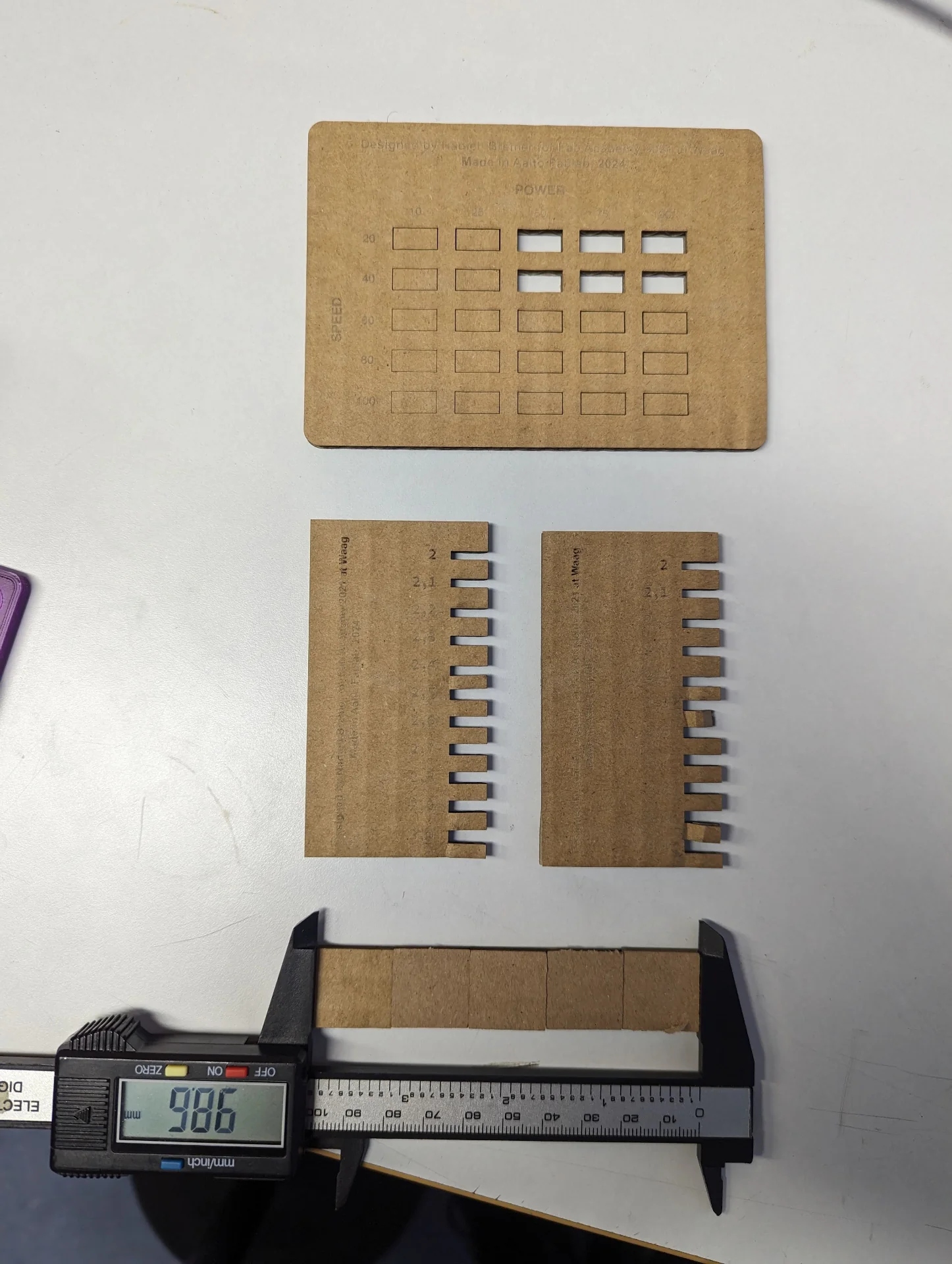
We had already measured the kerf and tried different power and speed settings during our introduction session back on Friday but, as the materials we created were still there on the table, I decided to make confirm our measurements once more. The kerf could be calculated by creating, for example, five 20mm * 20mm cubes, measuring their total width and dividng whatever was missing from 100mm by 5. In our case, this was (100mm - 98.6mm) / 5mm = 0.28mm.From the power and speed settings, I chose 75 and 40 respectively for a margin of safety. Before the second laser cutting introduction for the next group, I had just enough time to cut three pieces for experimentation, which turned out perfect cutting-wise on the very first attempt! This has probably never happened to me in my prior 20 years of life before so I was thoroughly elated.
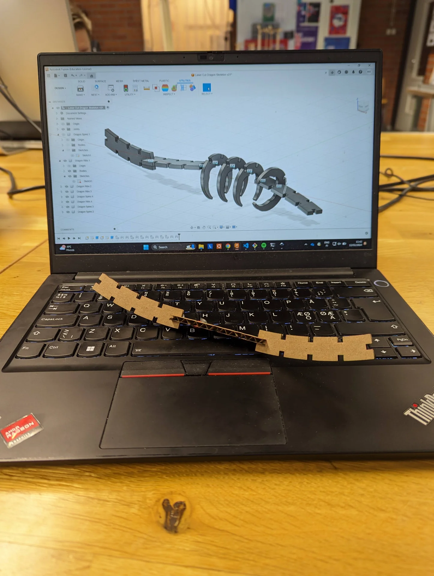
The settings produced nice, well-cut skeleton spine pieces that fit together snuggly, but I realized that they were too long and not steep enough in terms of their curvature for the application I had in mind. What is so amazing about parametric design is that to create an alternative version of the spine part, I merely had to change a couple of values (and sometimes, depending on their extremity, make only small adjustments to accomodate them). I changed their curvature to a mathematically more mutually compatible 30° (which refers to half-curvature, meaning that the entire piece is 60°) and reduced their length from 80mm to 60mm. The length parameters were named as such, but I noticed upon cutting that I had forgotten to divide them by two in my half-models leading to the double length, which was actually better in the end. The names still remain but they really only mean half a length.
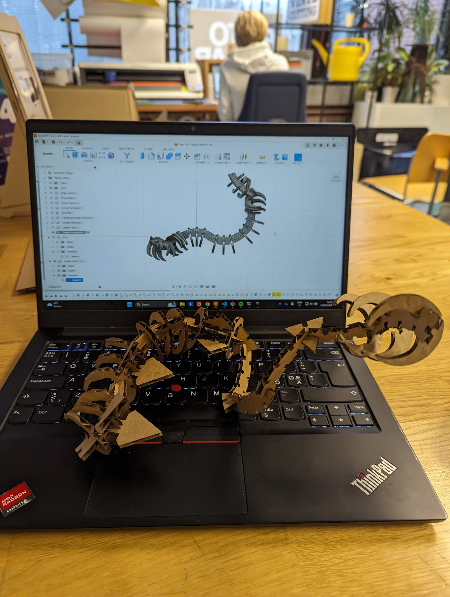
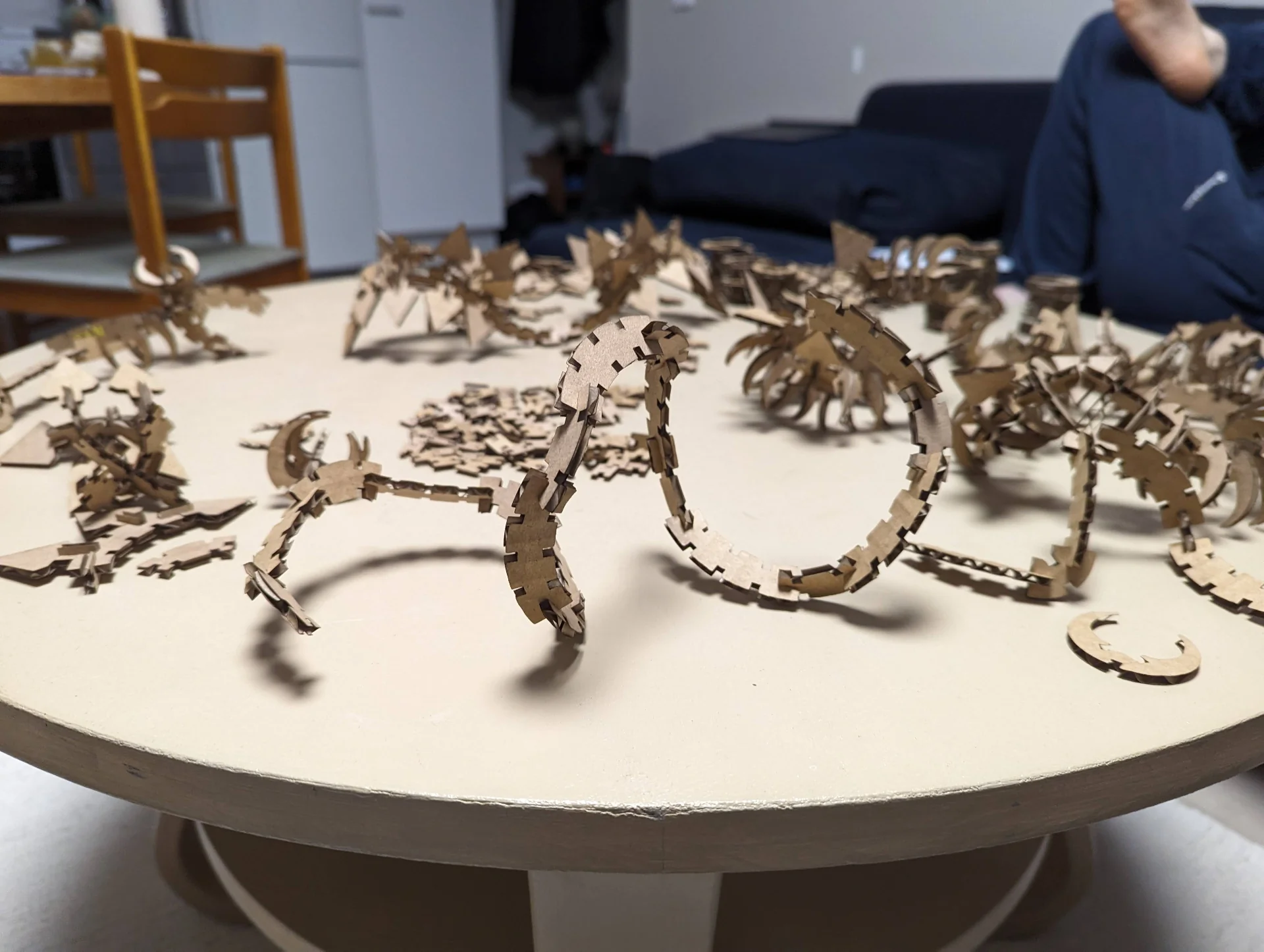
I also created an isosceles triangle connector and cut a few samples of them along with the ribs and the new, shorter and steeper spine parts. Below is what I had created by the end of Monday. I had plans for creating a separate piece to make the dragon head but this would have the difficulty of either being 2D or requiring a lot of detailed design work to make it coherently 3D. In the evening I just played around a bit with what I currently had, and even though this particular version looks a bit like a moose head currently, I much prefer a more abstract head, which is created from the same pieces, than a ready-made one. It saves me work and makes the kit as well as its users more expressive and versatile.
As can be seen in the first cut pieces picture, just a single type of ribs piece was not sufficient for smooth turns when two spine pieces were directly connected to each other. It looked better with a connector in between that made the curve less striking but I wanted more versatility. I thus created a variant on the ribs, which had two angular joints on the inside instead of one in the center, so that they could be placed at a less steep angle. I also created simple H-connectors for connecting spines together without turning, of which I also created a couple more variants for the possibility of tighter turns and different applications with even shorter spine parts and one even at a 45° angle. I also made the triangle connectors equilateral and created a seprate triangle-shaped fin component that would fit on top of the ribcages even when there were multiple in a row. The potential for different types of dragons was becoming exponentially more interesting with each component and then it was mass manufacturing time.
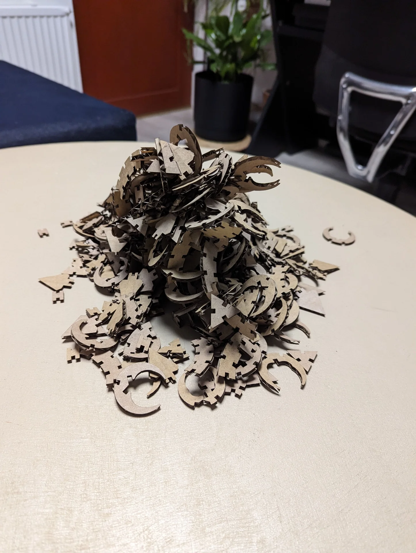
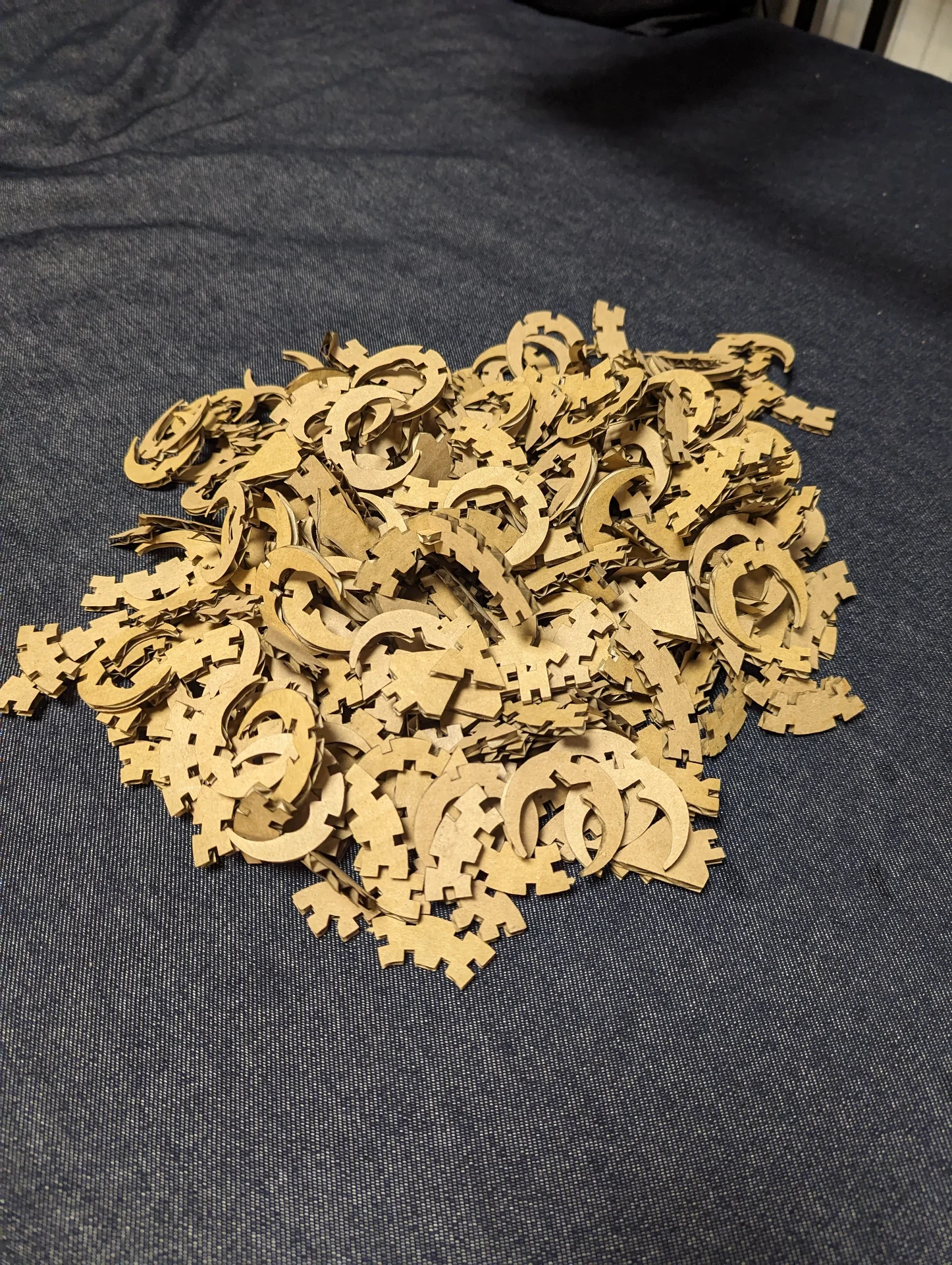
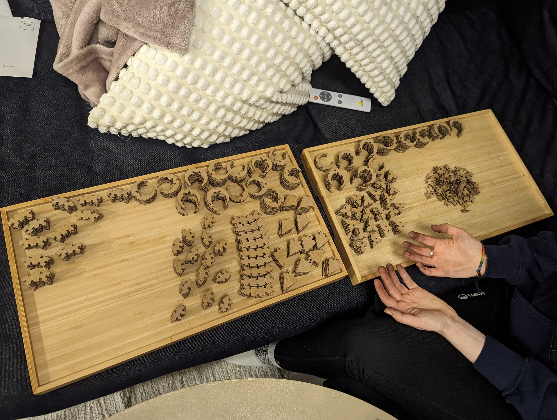
Thus far, I had been using a coursemates cardboard for my tests as he did not need it anymore and I had not dared to take an entirely unused one. By the end of the day, I had cut it up fully and I went home with a pile of dragon construction pieces with which we played with Rosa almost the entire evening. She made abstract art out the triangle connectors, which made me realize that those alone might already have been enough and plenty interesting for this week, and wings for the Chinese dragon whose spiral form I was trying to create in the meantime.
This culminated in the dragon in the cover image that now sits on my shelf but we did not manage to finish the larger, spiraling dragon. This was because I finally came up with a nice form for it as depicted in a barebones manner below. However, in my haste, I had not realized the the midsized spine (made by just scaling down the proper spine and removing the center joint) part had its two slits ever so slightly too near the ends as can be seen below if one looks closely. This meant that this was the only component whose all joints could not be used simultaneously, which had been a key design principle for all others.
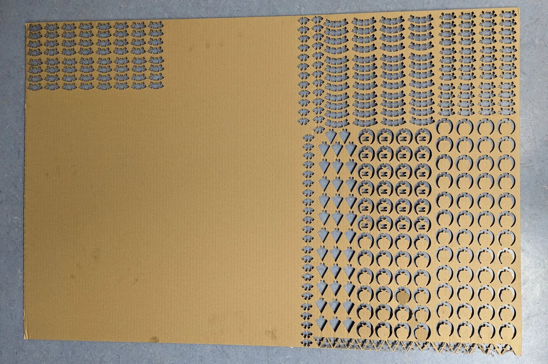
I fixed the midsized spine component by adjusting the constraints of the sketch and went back to cut them. Because I had to now actually take my own cardboard out and the one cut corner looked so lonely, I had to cut more pieces of everything else too. After all, I was on the global lecture with my phone next to me and I had nothing better to do while listening to it and there was no queue to the cutter. I then proceeded to cut a whole another kit from a bit less than half of the approximately 700mm x 1000mm piece of cardboard. Connectors I already had so many that I only made just a few more just for making it look nicer. Then I realized, however, that I had again cut the component with the wrong dimensions so then I had to start a new corner and cut what I originally had come in there for and finally all the components fit together perfectly.
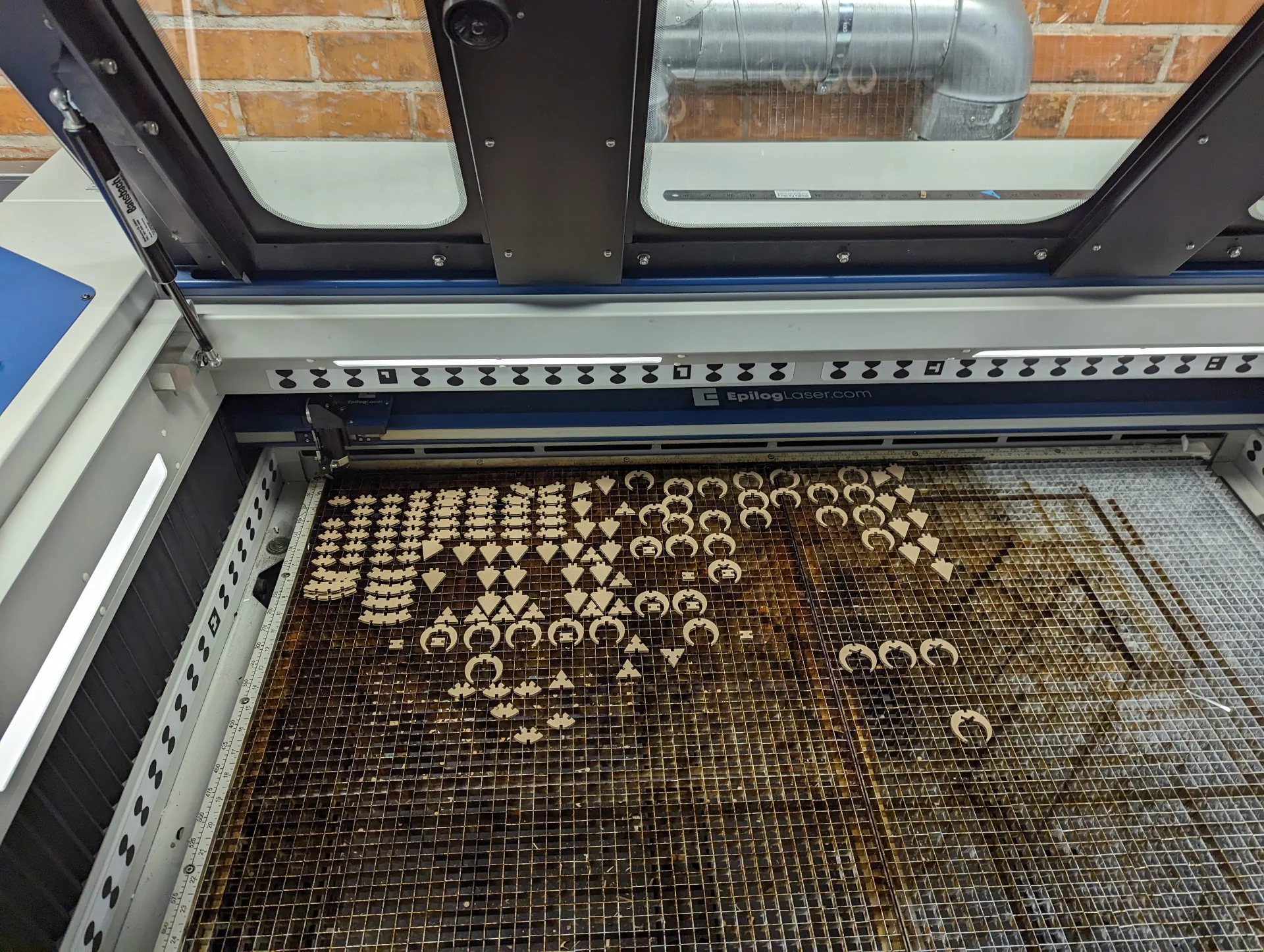
Cutting this entire set with speed of around 30-35% took approximately 55 minutes. What was highly peculiar about our laser cutter was that it was at its most efficient at the upper left corner and the further away from there it got, the less efficient it became and the more the pieces had to be separated from the cardboard manually. Whereas initially, with lower numbers of parts cut at once, I had been more careful about doing so, with this large of a batch, I realized that it was much faster, easier and probably neater too to just forcibly poke them out, which created just as good - if not better - results than trying to separate them overly carefully.
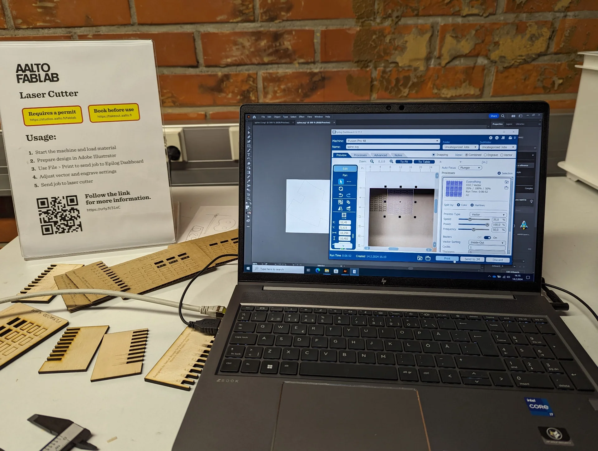
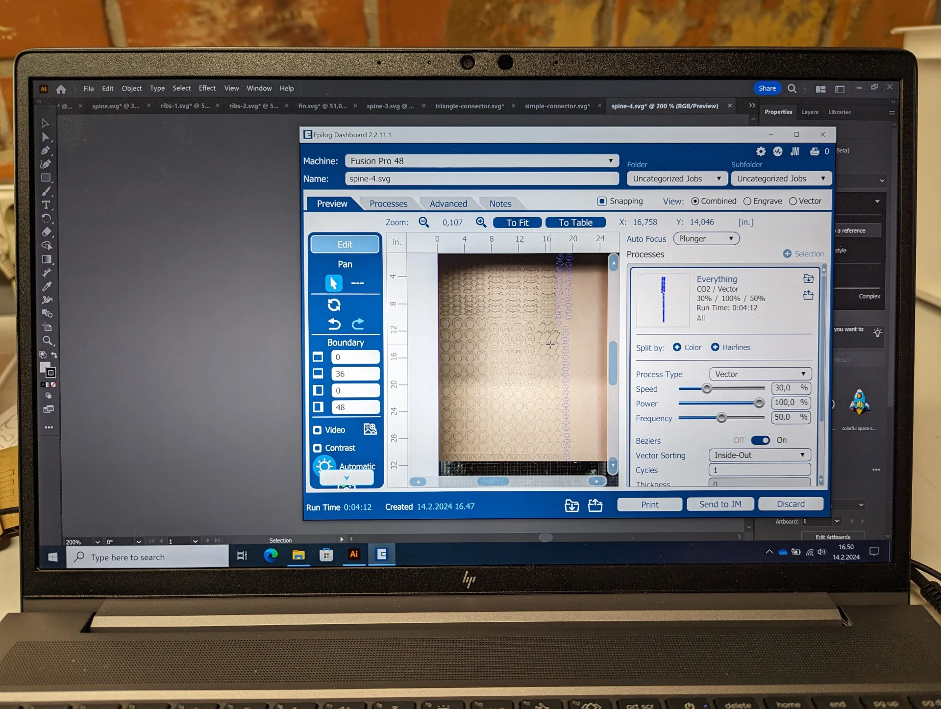
The effect of this radius of efficiency was so strong that 40% speed and 75% power were just fine say, on a 15 centimeter radius but outside of it, power had to be increased and speed decreased. I eventually ended up using 30% speed and 100% power as my default setting if I was at all further from the corner and even then I often had to poke the remaining pieces out. In the picture below, these settings can be seen with “Auto Focus” set to “Plunger” and an estimated run time (which is very accurate) of 4 minutes and 12 seconds for the pieces highlighted in blue. Perhaps because of everywhere reading “Print” I had to go throuhg this text multiple times to go replace me talking about printing with cutting but here too “Print” button is what sends it to the machine, where just pressing play makes it go.
The Dragon Kit
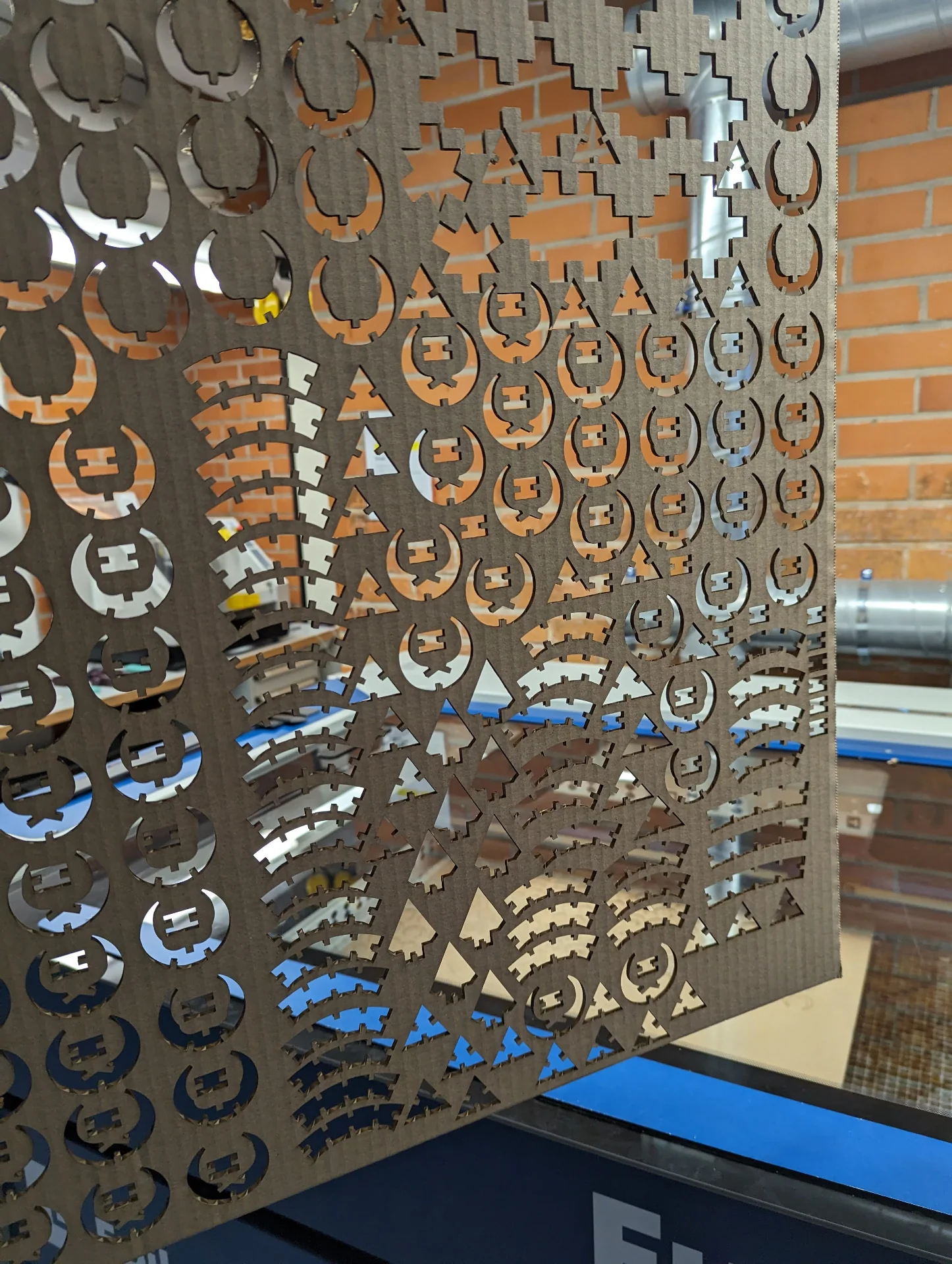
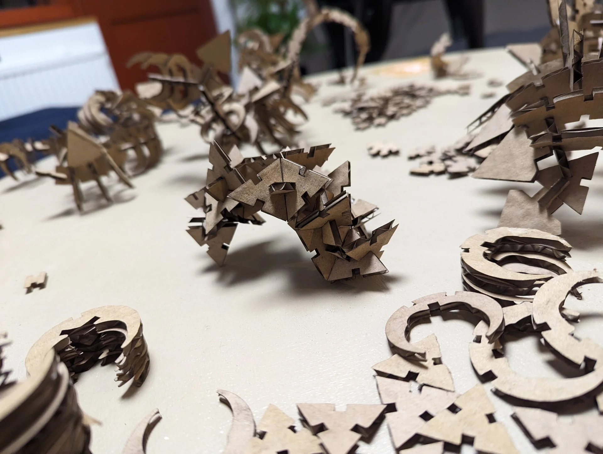
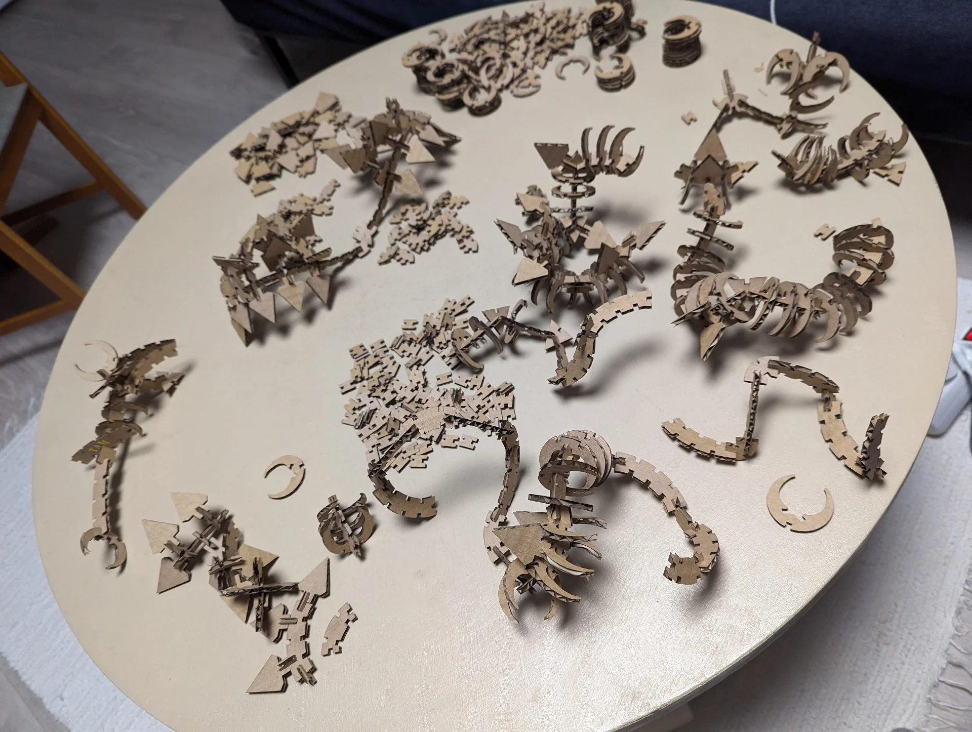
The final parametric press-fit dragon construction kit consists of eight different pieces portrayed below. There are three spine variants in total, two of which with curvature 30° and lengths 60mm and 40mm and one with curvature 45° and length 30mm, each with a different number of slits from 4 through 6 and up to 8. There are two ribcage variants, which, when placed on spine parts directly connected to each other, form approximately a 45° angle with each other for improved continuity in turns and spirals. Applications in the context of dragons or dinosaurs can also include, for example, horns, claws, nails and teeth. Then there are fins and two types of connectors, namely equilateral triangles, which alone can be used for all kinds of interesting constructions and the simple H-connectors to enable connectivity between pieces such that they lie on the same plane.
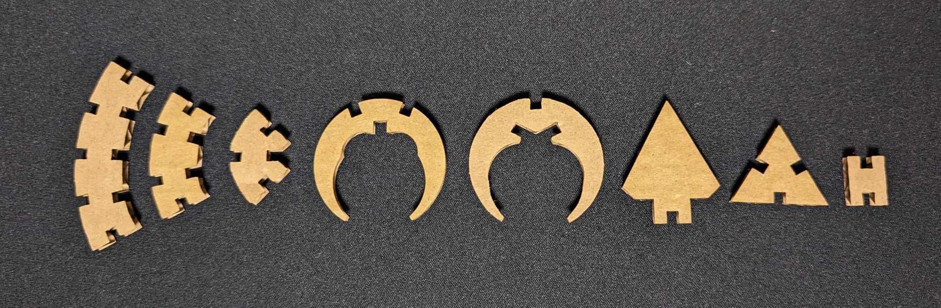
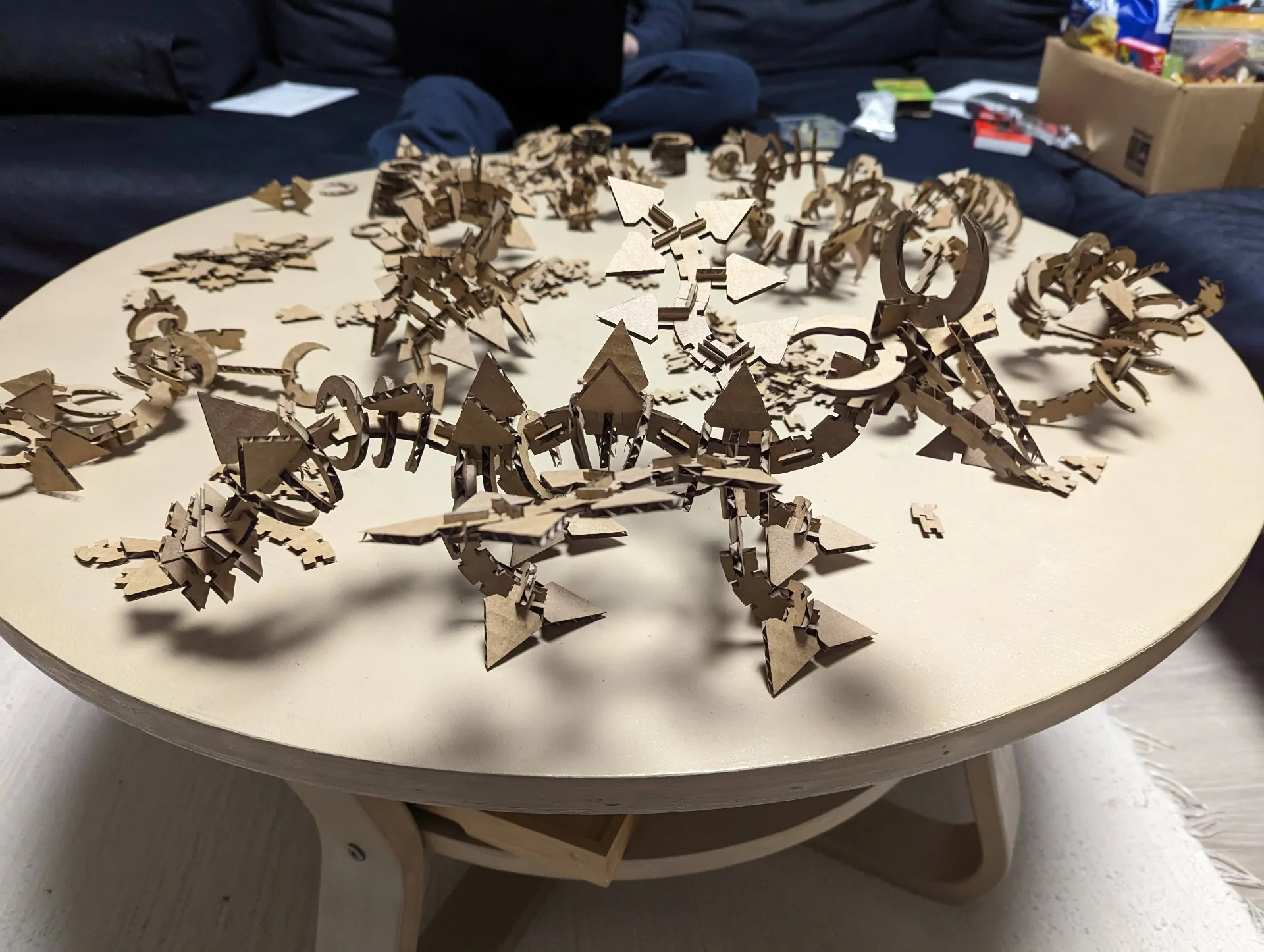
The design of the kit intentionally avoids straight connections and sharp angles and while its primary use case thus far may be dragons, it is very well suited for almost anything organic whether that is dragons, dinosaurs or palm trees. It could be the perfect gift for crafty builders or archeology enthusiasts although it must be warned that at least the cardboard version smells a bit and really dirties ones hands when handled on the same day that they were cut. In fact, I plan on still building the other dragon spiraling up our shelf but what remains after that, I might give as a gift to my little brothers and see what kind of dragons they will build or if they will go for something else entirely.
The files for cutting and modifying the pieces can be found in the repository here under “content > post > week-3” in .f3d, .step, .dxf and .svg formats, first two of which are for parametric 3D modeling and the latter two being suited for cutting. Feel free to cut your own kit for personal use and share your creations with me on any of the platforms found from the column on the left if you do!
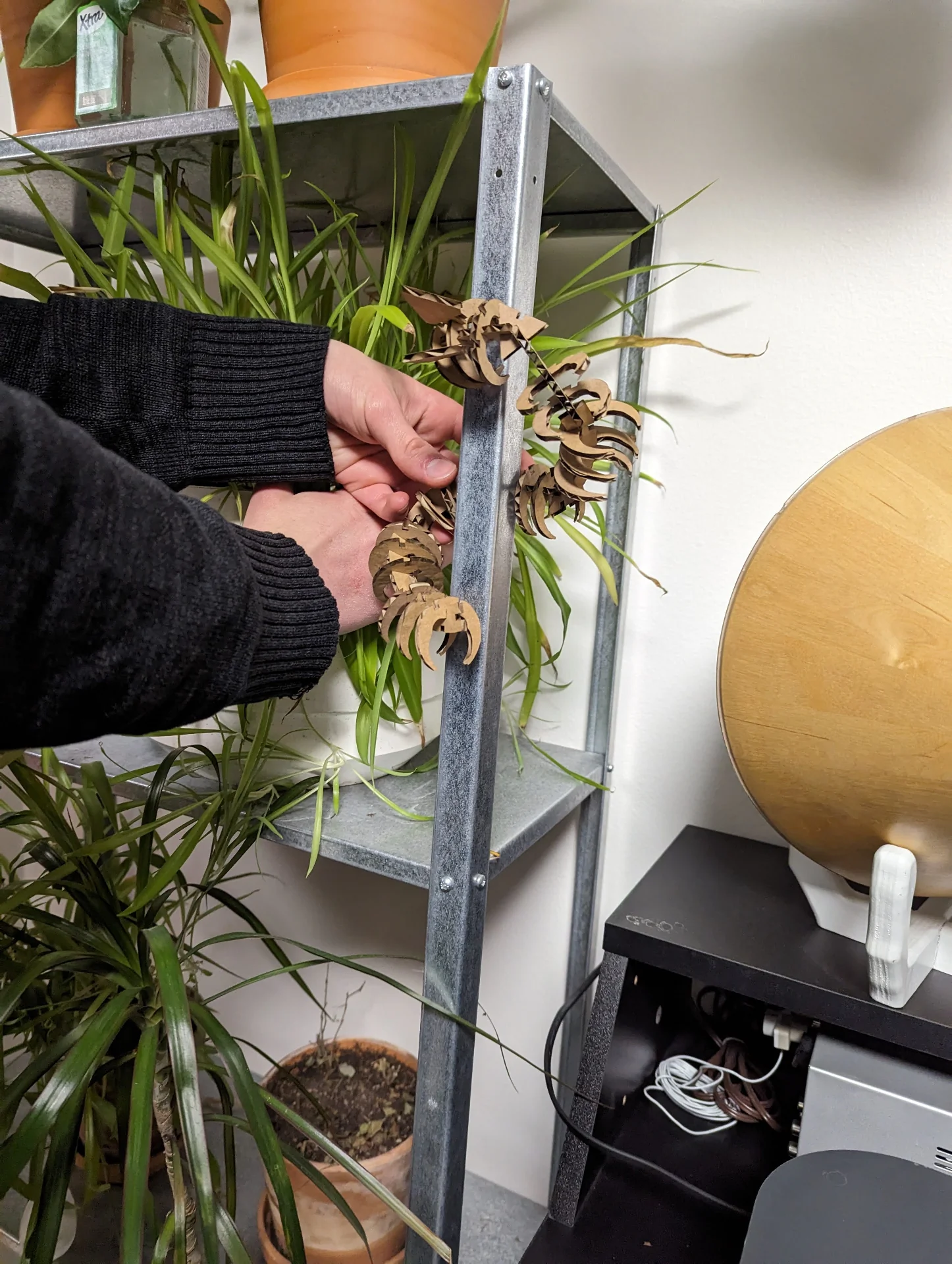
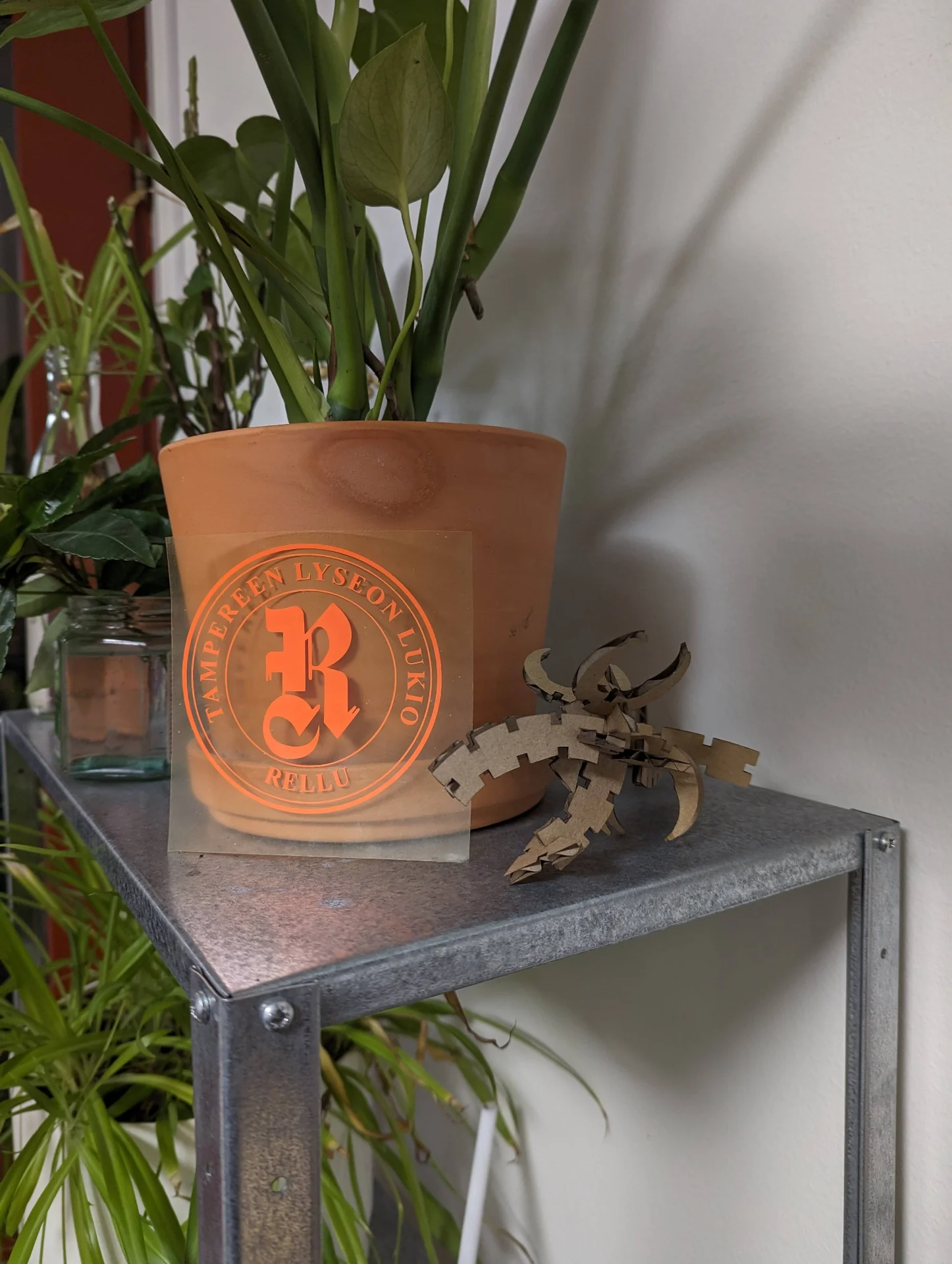
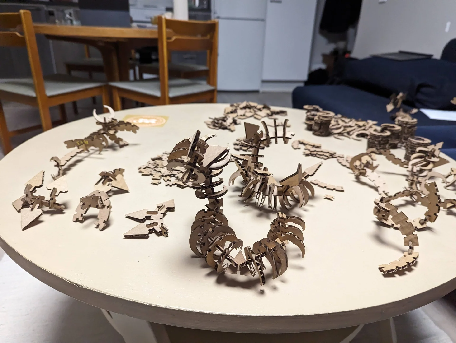
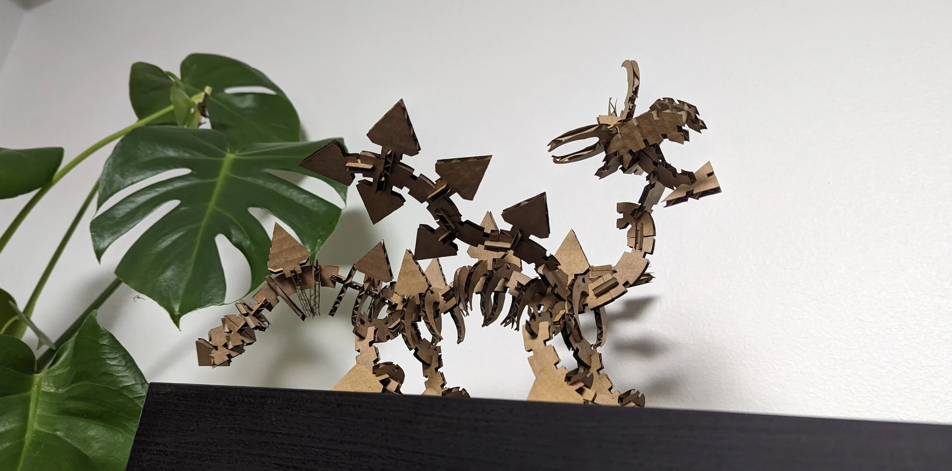
I have not yet had the time to fully assemble the Chinese Dragon, but I will update it here when I do. In the meantime, do enjoy the more western variant below! By the way, it is also assembled entirely without any glue and has stood firm for a couple of days already with no sign of anything going against that in the future either. If it gets boring or we move, we’ll just dissassemble it and create something new out of the versatile pieces.
Reflections
This was an amazing week! Not the least because I got to play with construction sets again - and not only any sets but self made! I have missed my legos, most of which I left home at Tampere when moving to Otaniemi, and building my dragon reminded me just how much. I do have a Lego Mindstorms EV3 here that I should tend to when I finally get the time but that’s it. Even so, I think this was even more fun and amazingly gratifying!
It was a lot of work too and a lot was learned. Mainly about double-checking things perhaps. Make sure that the vinyl is the right way around and the cutting area is large enough. Make sure that the pieces always fit. Constantly make and test samples. Ask others how they tackled similar issues. Be creative and most importantly, have fun!
Creativity is tough when you have to summon it on a tight schedule but pressure also makes diamonds. The opportunity cost of brainstorming, which sometimes results in gold and other times in gravel, is difficult to compare against more linear courses, where you just have to solve a set amount of problems and are then ready. In a way, I am thus looking forward to next week’s electronics production, where Neil Gershenfeld warned that there will be almost no creativity as then I get to catch up a little on my three other courses and maybe catch my breath a bit otherwise too.
Too much freedom often leads me to overshoot my projects a little bit but on the other hand, it always feels fantastic to be on the other side of them afterwards. But I would definitely say that this alternating pace of highly creative work every other week and learning a new skill on more solid guardrails every other week sounds pretty good. It is like a scrum sprint with a two-week period but where you immediately switch projects instead of iterating. All in all, it might take a little while but I already can’t wait to build my next dragon and a laser cutter will definitely be something found from my garage one day!