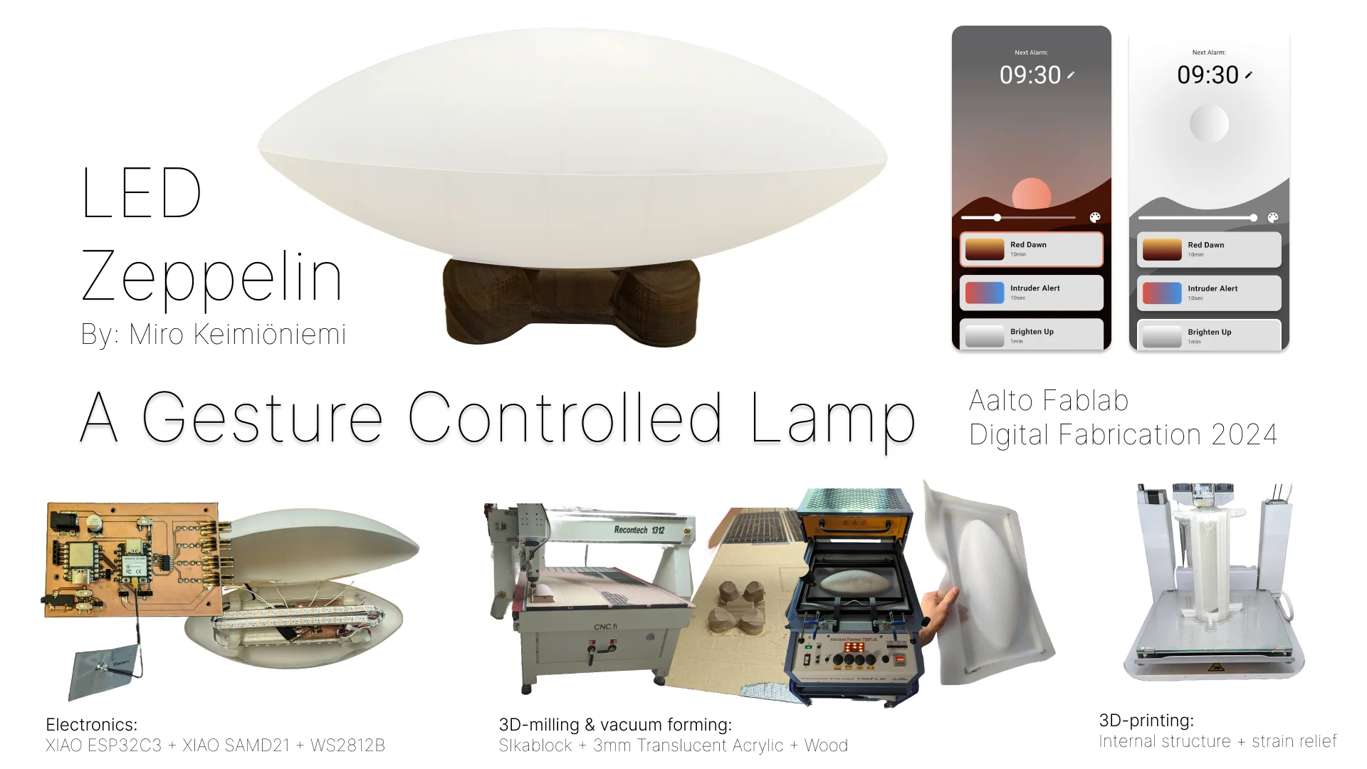
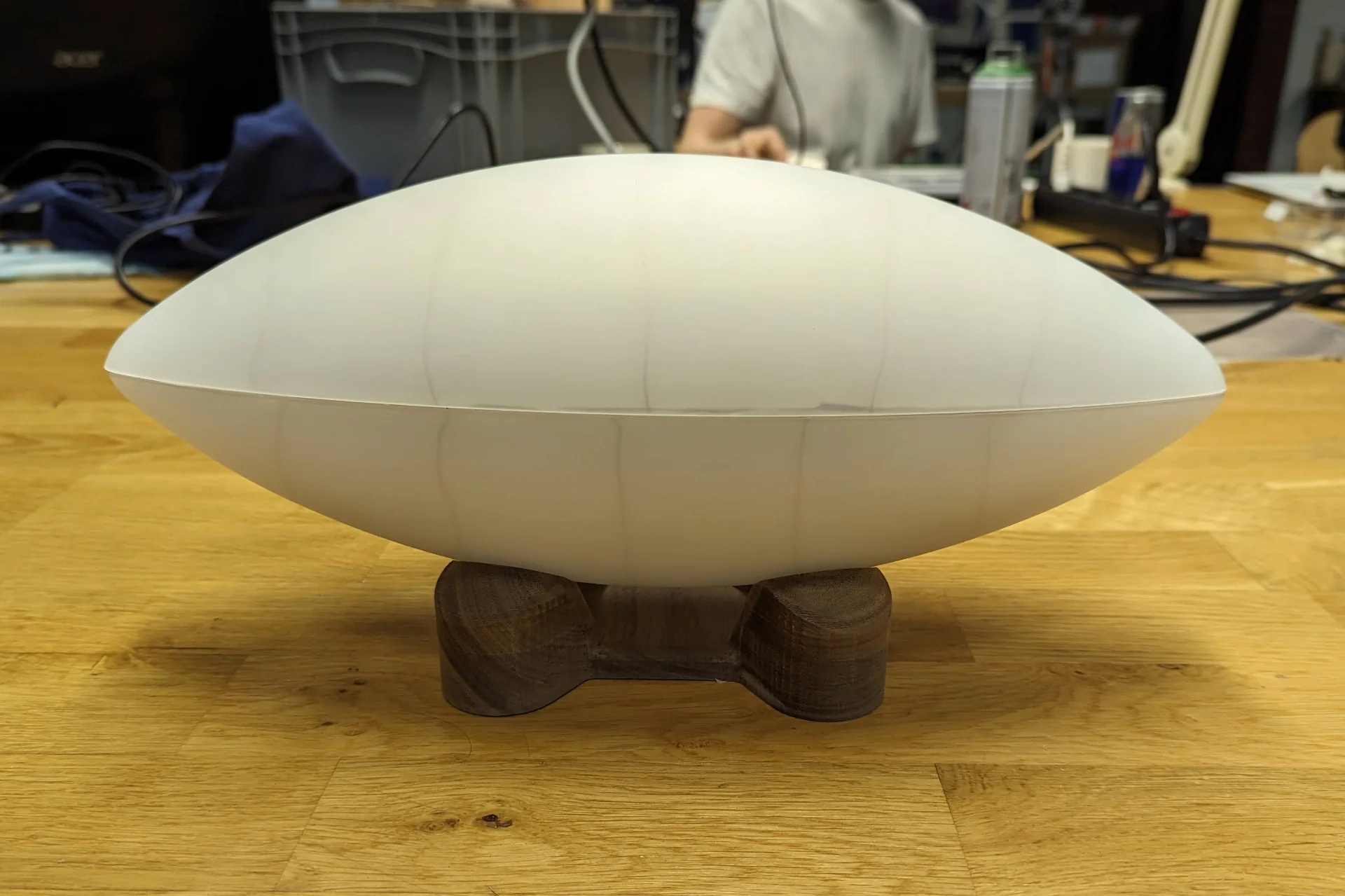
The LED Zeppelin is a custom gesture controlled sunrise alarm clock lamp, where all the electronics are contained within the ellipsoid diffuser, that can be placed on or inside various different kinds of separate stands. It works as a regular lamp by tapping it to turn it on or off and swiping towards either end to adjust its brightness either up or down. The alarm clock functionality works via a mobile app where you can choose an animation including a sound that will start and reach its peak at the times set. The app can also be used to change the color as well as fine tune the brightness.
Demo video
Watch a less compressed version of the demo video on YouTube. The music on the video is an old unfinished beat of mine, which I threw on it at 2am as I could not be bothered to start searching for royalty-free music at that point.
Hero shots
Bill of materials (BOM)
Below is a table of all the materials and components used along with their current price estimates:
| Item / material | Quantity | Price |
|---|---|---|
| 3mm translucent acrylic | 1 large sheet | 15.09€ |
| Hard wood | 15 x 12 x 4.5 cm block | 15€ |
| FR2 copper | 1 sheet | 5€ |
| Transparent PLA | 240g | 5€ |
| LED diffuser foam | 1 sheet | 12€ |
| PEAMD50-10-B2 power supply | 1 | 23.70€ |
| XIAO SAMD21 microcontroller | 1 | 4.99€ |
| XIAO ESP32C3 microcontroller | 1 | 4.61€ |
| TXB0104D level shifter | 1 | 1.26€ |
| PJ-002AH-SMT-TR power jack | 1 | 1.14€ |
| 220µF capacitor | 1 | 0.5€ |
| Slide top switch | 1 | 0.6€ |
| Schottky diode | 1 | 0.5€ |
| Resistor | 10 | 0.9€ |
| Pin socket | 5 pins | 0.5€ |
| Pin header | 12 pins | 0.5€ |
| Total | 91.29€ |
The above table is only constructed from the items and materials that currently make up the lamp and are actively used, excluding, for example, the 3.5mm audio jack and the hard-to-quantify-at-this-low-of-a-level consumable stock such as wires, dupont connectors, zip ties, adhesives and tape, as well as the SikaBlock and the glue used with it and other materials and tools similarly used in the manufacturing process. Furthermore, many components were difficult to pin down exactly and thus all prices without two decimal numbers represent rather the orders of magnitudes for that quantity of the given component instead of exact prices.
All of the prices of the electronic components are taken from DigiKey either as the exact prices or averaging over some reasonably similar components, whereas other materials are looked up from the Fablab pricing or other sources from the internet. I noticed only afterwards that the prices from DigiKey are without VAT, so for regular consumers, 24% must be added to the prices of all electronics, hence bringing the total up to 100.7€. Accounting for wires, dupont connectors and everything else that was failed to be mentioned, it likely climbs up to 105 - 110€ conservatively and this of course does not include all the experimentation, failed attempts and intermediary material.
It must be noted though, that all the prices are looked up rather quickly so they are likely far from the lowest. Furthermore, they are non-bulk prices so that, for example, the DigiKey prices that were looked up, were only for single components. The prices of sheets are not necessarily for the exact sizes that were actually used in two ways: the sheets themselves might have been slightly different sizes and much of the sheet might not have been used so that they can still be used for other projects. The prices listed are nevertheless for the whole sheets. The price can certainly be pushed down by a fair margin by choosing different variants of components, buying them in bulk and sourcing them from different sources but replicating the project with access to appropriate machinery can be expected to cost well over 100€ particularly when adding the costs of SikaBlock, tape, adhesives, wires and other consumable stock.
Creating physical prototypes can get expensive very quickly - for a student anyway if we had to purchase everything ourselves. Luckily the course let us explore and focus on learning instead of making us worry too much about the prices of particularly our failures too early in the process, where that might have been somewhat paralyzing.
Plan, progress and timeline
I am not aware of any prior, similar projects although I am certain that they do exist and am open to mentioning those here if they are pointed out to me. All the material that I have used such as tools, tutorials and documentation can be found as links at the relevant points throughout my documentation.
As can be seen in the documentation section, I personally designed and manufactured the PCB used to control the LED strips, the logic running on the microcontrollers, the diffuser, the stand, the internal structure and the app used to control the lamp. These were created from the materials mentioned above in the bill of materials (BOM) and further explained in their respective documentation, most of which came from the Aalto Fablab inventory with some of the electronics not found on the Fab inventory, such as the power supply and the level shifter, being order from DigiKey. Their costs are approximated above in the BOM.
The PCB was designed in KiCad and made by milling an FR2 copper sheet and soldering on the surface-mount components (/devices) (SMD) as documented below. The diffuser, stand and the internal structure were designed in Fusion 360 and made by 3-axis milling double-layered SikaBlock and vacuum forming 3mm translucent acrylic over it, 3-axis milling and 3D-printing respectively so that both additive and subtractive fabrication processes were utilized.
The most central questions to be answered during the project included mostly practical ones about which materials and processes to use for manufacturing the diffuser, how to detect the gestures in both hardware and software, how to drive the LEDs in spec in the most sensible way, how to avoid shadows inside the lamp as much as possible and how to deliver enough power to the LEDs, while still taking account safety both of the board and the users.
Below is the to-do list and the shchedule for answering the questions and producing the results that was used in development. Now, after the project has already been completed, the deadlines refer to the days of completion and the “Done” statuses link to the relevant documentation pages. The notes section below the table lists some of the questions in more detail with then preliminary potential answers as well.
| Task | Status | Deadline |
|---|---|---|
| 1. Design the lamp and a stand | Done | 29.5.2024 |
| 2. Design touch detection circuit | Done | 10.4.2024 |
| 3. Program touch detection circuit | Done | 27.4.2024 |
| 4. Implement gesture detection | Done | 27.4.2024 |
| 5. Design output circuit | Done | 11.5.2024 |
| 6. Program light animations | Done | 6.6.2024 |
| 7. Program ambient sound output | Omitted | - |
| 8. Program inter-board communication | Done | 15.5.2024 |
| 9. Design power delivery circuit | Done | 19.5.2024 |
| 10. Combine circuits and produce the result | Done | 15.5.2024 |
| 11. Design mobile app | Done | 8.5.2024 |
| 12. Implement mobile app with Flutter | Done | 2.6.2024 |
| 13. Program wireless networking with mobile app | Done | 6.6.2024 |
| 14. Design the internals and the ellipsoid lamp cover | Done | 29.5.2024 |
| 15. Produce the lamp cover | Done | 30.5.2024 |
| 16. Assemble the lamp | Done | 4.6.2024 |
| 17. Produce the stand | Done | 31.5.2024 |
| (18.) Design and produce an alternative stand | Optional | - |
| (19.) Add long touch and double tap gestures | Optional | - |
| (20.) Give the lamp a personality | Optional | - |
| (21.) Proximity detection using e.g. Bluetooth | Optional | - |
| 22. Make a presentation page and video | Done | 7.6.2024 |
Notes:
- Output circuit must be redesigned using level shifters in order to use 5V power for NeoPixels with 3.3V logic. 3.5mm audio socket pins must also be routed correctly. NeoPixels and level shifters are both already procured and available at the FabLab.
- Light animations can be programmed among the last tasks when the lamp is already assembled so that they look as intended.
- Likely need to purchase a 5V power source capable of 9A as I could not find one at the lab. ESP32C3 can be powere on from its 5V pin with a diode but SAMD21 must be considered separately.
- 3/4D mill a sikablock to produce half an ellipsoid diffuser by vacuum forming 3mm translucent (or white) acrylic already available at the lab.
Using Roland Modela MDX-40 might require a more elaborate design, where the piece to be vacuum formed might have to be produced in several layers. It, however, might not have sufficient length dimension either so 3D-axis milling with the larger CNC might be the best idea. It is a good idea to account for the fillet at the base of the mold by making it a bit higher than what the vacuum formed product should be. Remember to measure the height possible for a 3D-milled ellipsoid.
- Design a separate 3D-printable framework that safely suspends the circuit in the middle of the lamp from supports whose lengths correspond to the exact radius of the ellipsoid at the given positions. The circuit board can be fastened to it with screws and it can be fastened to the lamp cover with some kind of adhesive. With good design and little transportation, it might not have to be fastened at all. It is also obviously highly important to leave a hole for the power cable.
- Flexible copper strips soldered to jumper cables can be attached to the underside of the diffuser from their adhesive sides as seven looped stripes around the long axis. The internal frame can be fastened to one half with a strong adhesive and to the other with a slow one upon closing the ellipsoid. Alternatively, it does not have to be fastened to the other side at all. In this case, I could make the cover openable with some sort of a snapping mechanism, which is likely much harder to make but would make the lamp easily repairable.
- 3D mill a wood block.
- Make it behave like a luminous pet or a spren (from The Stormlight Archive) that turns on dimly when detecting proximity and might occasionally want attention, which it communicates by changing its hue until acknowledged with, for example, a long touch to which it might respond with some different light pattern. It could be made to track, for example, a habit or whether one had a good day. It could also be linked with another similar lamp such that if it is being touched for long, the other lamp lights up the area that is being touched and one can thus, for example, say a personal good night with it. In the long run it could even be made to talk and listen with additional hardware capabilities but those are definitely beyond the current scope.
Ideation
Having to come up with a final project idea as pretty much the first thing without knowing how everything works caught me a bit off guard but it does make sense in the context of the course as it is so intense, fast-paced and packed with both information and assignments. Having a final project thought out in the very beginning helps you orient your approach to each week and know what you most need to focus on. For example, as a result of the below brainstorming and committing to an idea, I knew that I needed to focus especially on LEDs and speakers on the output week. It was a long road to arrive at the idea, however, and what follows is a dump of some of the ideas I got, considered and eventually discarded.
The ideation phase is often very long for me as I always want to create something somehow meaningful, whether that is in a local or global context. For this project, it seems to make more sense to go local as that is, according to my understanding, in some sense the very ethos of the fab movement. I had a cool idea for remote chess boards but am a couple of years late, because those have already been producticed and commercialized by, for example, ChessUp (although I think I could make them nicer looking), which was both cool and a bit of a bummer. Maybe I will make them nicer looking and/or cheaper and compete that way one day.
After discovering this, I lost my appetite for the idea and tried turning to solving some personal problems instead. The only issue is that I currently cannot come up with too many problems I would have - how incredible is it to live in Finland and be in a modestly decent fiscal situation for a student? - so there were no obvious project ideas for this particular scope. I still do have many ideas but many of them were not directly suitable for this course. I kept on wondering about another remotely playable board game but after extensive research, I could not come up with any other the playing experience of which would be significantly improved over just a digital version. I would then have to create a new game myself, which I opened as a background tab in my mind and still keep there. However, here are the results of my further brainstorming within the bounds of the course:
- Luminous remote chess
- Remotely playable board game
- Connected, re-arrangeable statues that mirror each other’s shapes. For example, a rigid string that can be folded to a shape, causing the other to take the same shape
- Remote drawing / writing inspired by spanreeds from The Stormlight Archive
- 3D printer that scans the item put inside it and then replicates it
- Box that opens only when a task is completed (can be used for locking away one’s phone or to keep a reward)
- Physical wave synthesizer that produces sound corresponding to the shape of a string (sine, saw, square etc.)
- Midi controller
- Mood lamp
- Wall clock
- Bright light alarm clock
- Something for a bookcase (physical reading challenge / art?)
- Weasley clock
- Lightsaber laser pointer
- Perpetual motion machine
Most interesting avenues:
- Action at a distance / “Magical items”
- Remotely playable board game
- Kinetic statues
- Weasley clock
- Spanreed
- Lightsaber laser pointer
- Productivity boosters
- Innovative alarm clock
- Phone / reward locker
- Year progress bar
- Task / mortality visualization
- Midi controller / instrument / player
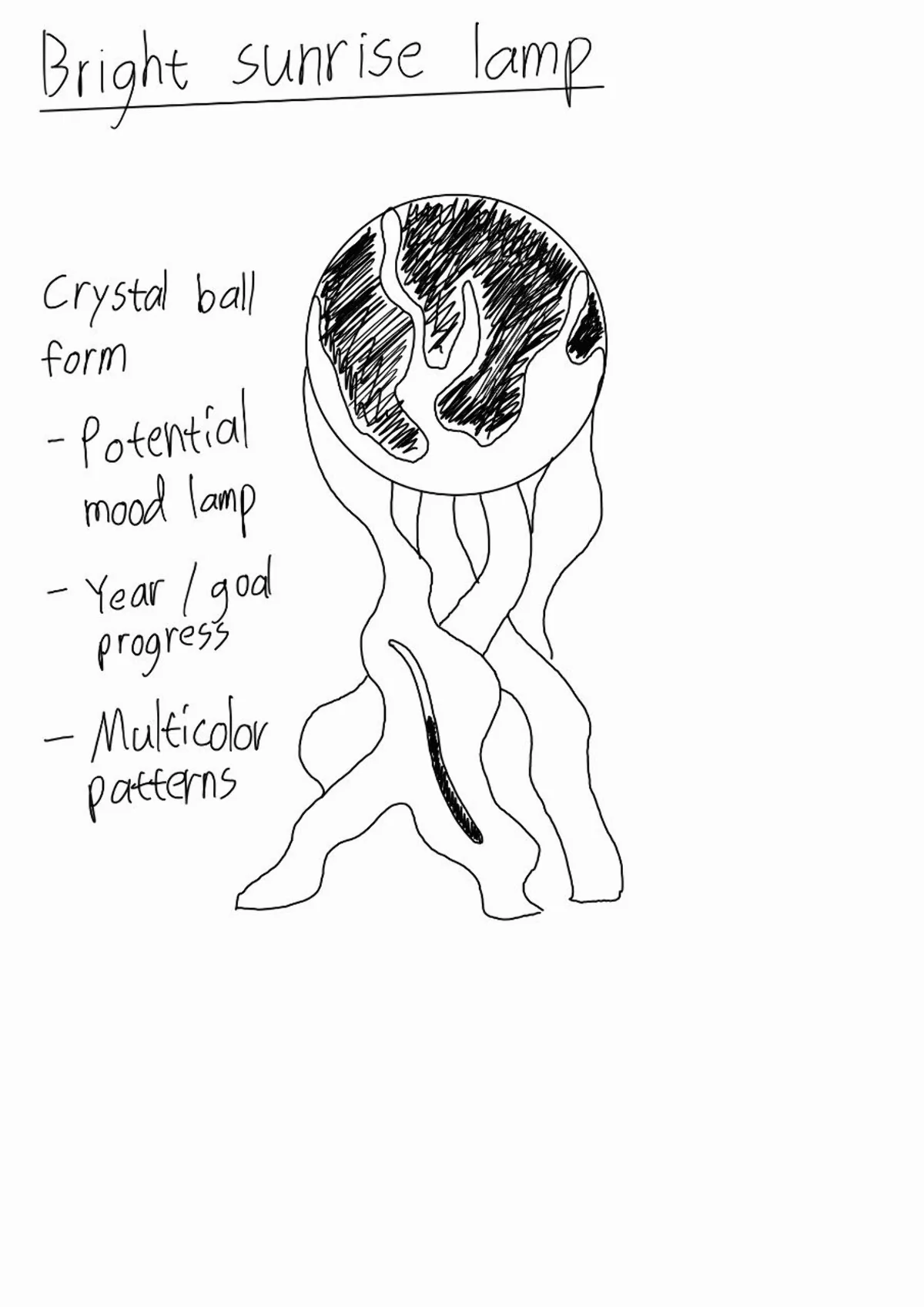
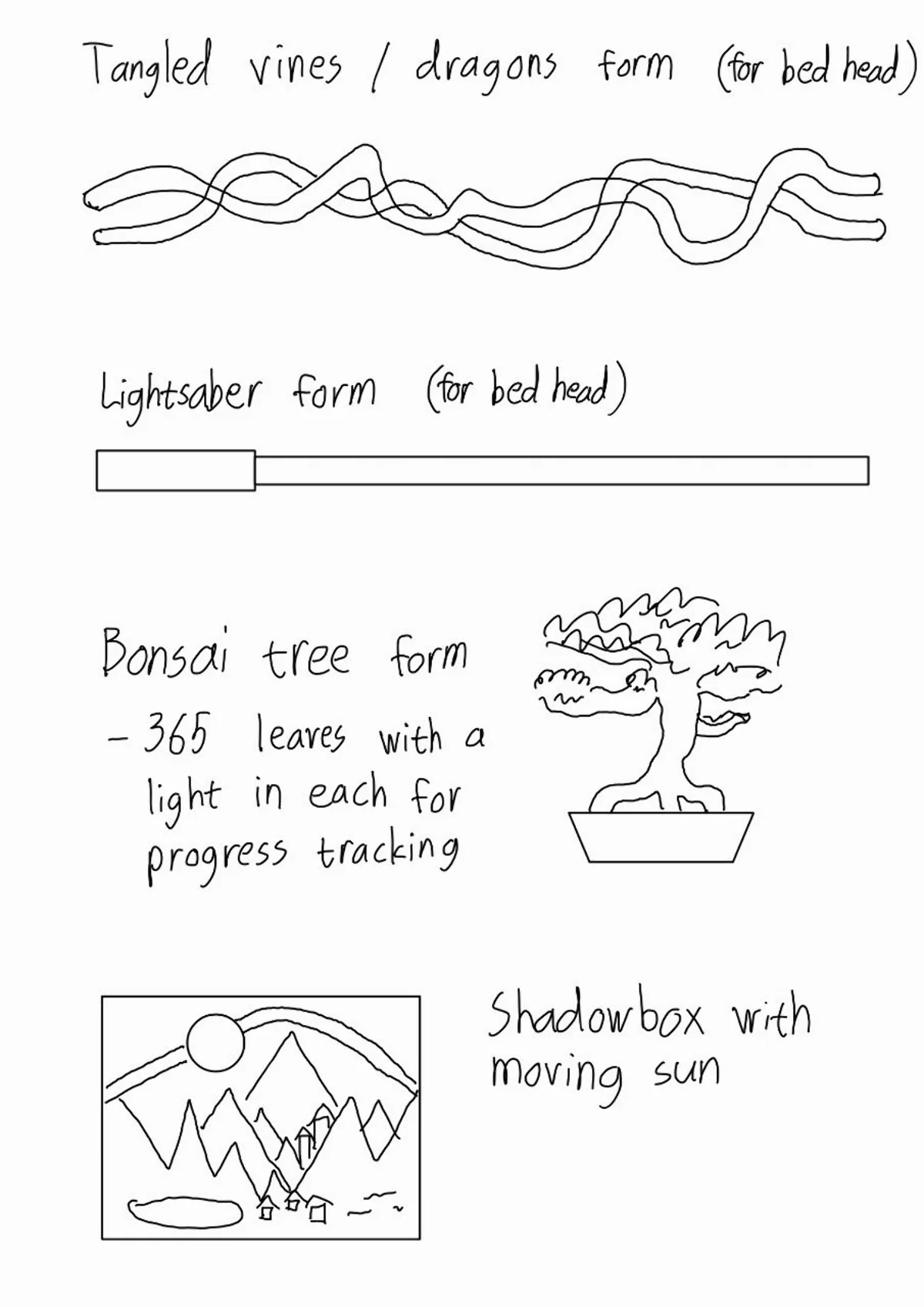
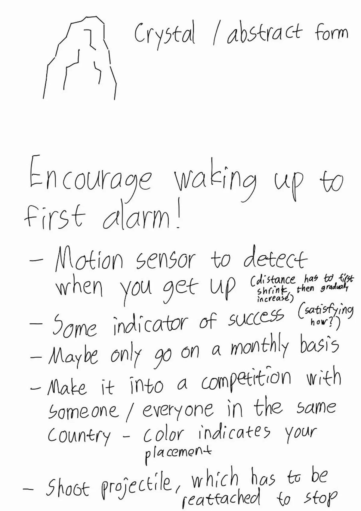
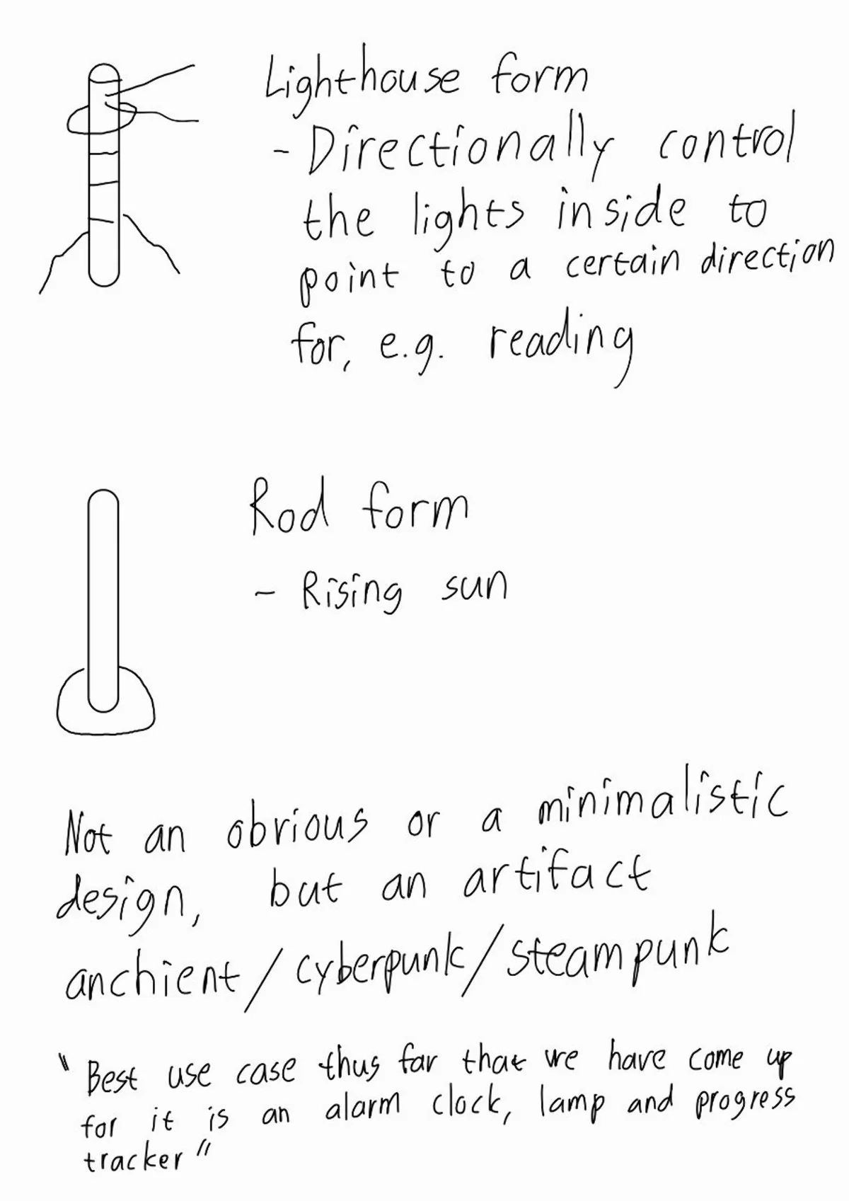
I ended up leaning toward creating some kind of an alarm clock / light that would wake me up to a simulated sunset. Many exist already, but they are kind of expensive and boring looking so the point here would prehaps be either the design or adding some cool feature that they do not have, at least in lower pricing points. With my non-existent drawing skills, I sketched a few ideas on Samsung Notes with my tablet. They look pretty horrendous due to being incredibly quick, not being drawn in an app made for it and being drawn by me, but perhaps they might still be somewhat representative of the general thought process.
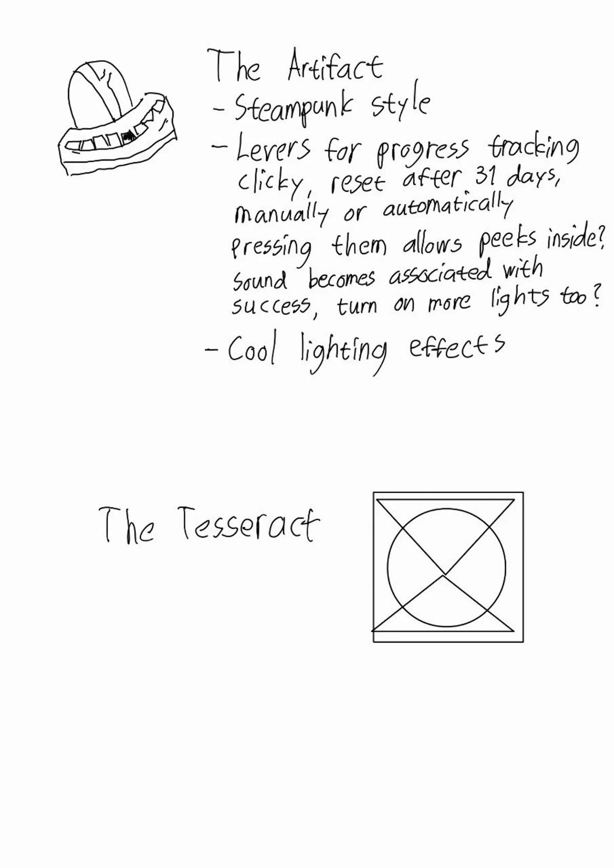
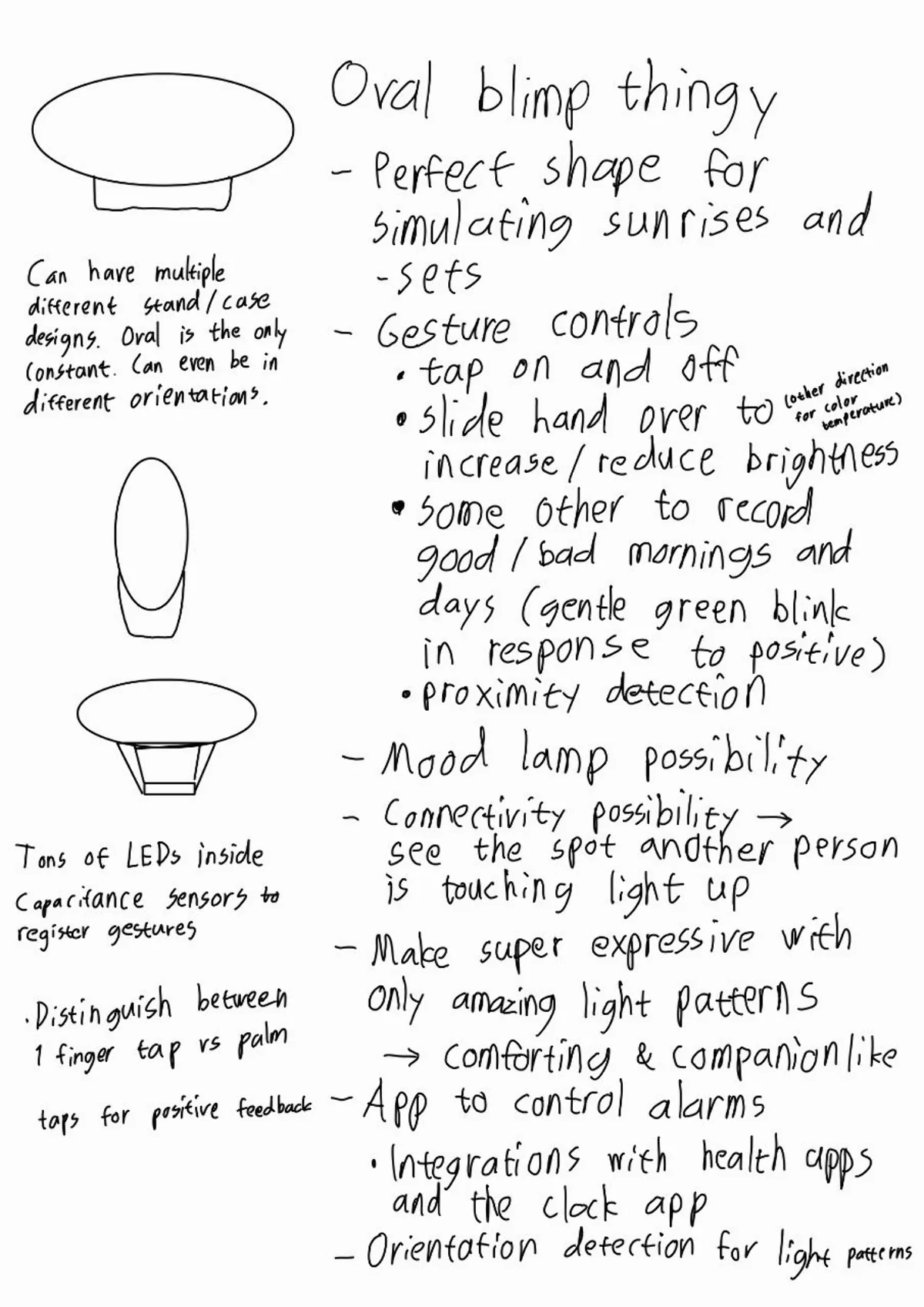
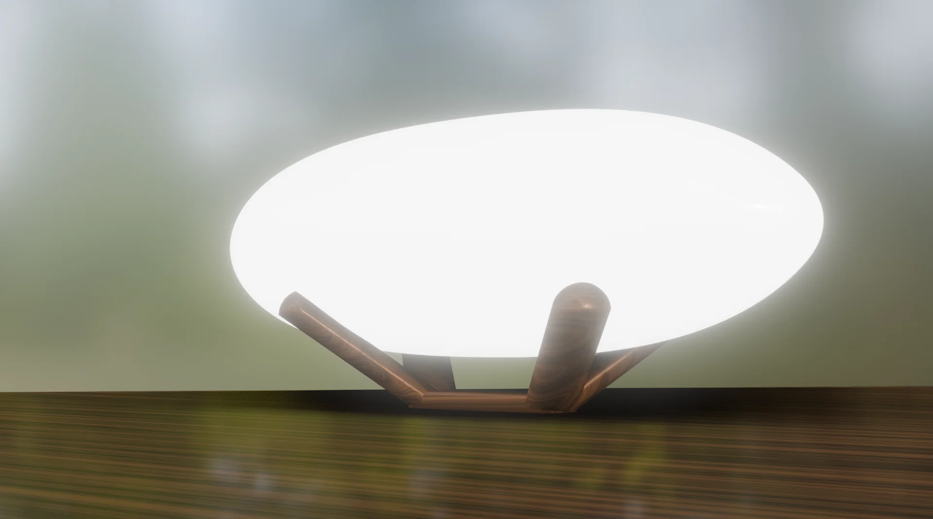
I grew very interested towards the last one “Oval blimp thingy” that I then renamed to “gesture controlled bright alarm lamp”, which Rosa suggested should be called the “LED Zeppelin” due to its resemblance to a zeppelin and the resulting pun. It was actually a real shower thought stumbled upon when pondering possible interesting shapes for a sunrise alarm clock. I think I was drawn to it for its elegance, where the oval is the perfect shape for simulating sunrises and sunsets. All electronics would be packed inside of it so that the stands could be changeable and thus a bit more of a design element that can go anywhere from minimalist to elaborate.
It also provides the perfect range of scaling challenge. Its primary function would be to function as an alarm clock that simulates a sunrise with independently controllable LEDs inside. The alarm would be set in a simple app that communicates with the lamp over Bluetooth to set the times for the alarm (integration with native clock apps is also an interesting potential avenue for exploration). A built-in speaker could also play some noise that increases in volume with the brightness. The secondary functions would be gesture controls, where a whole palm touch would turn it on and off and sliding one’s hand over it would increase brightness in one way and reduce it in the other. The tertiary function would be to control the colors from the app in some unified way and make the brightness control dynamic such that lower brightness levels are warmer and higher are cooler.
An interesting addition would also be habit tracking, where, for example, a one fingered tap is a positive note, to which the lamp would react by a brief, gentle green blink and catalogue that in the app, where it could possibly be elaborated upon or just left as a positive mark. The ranking is based on which functionalities I would most need but it might be that 1 and 2 change places too. Achieving all of these would be perfect but there are also further expansion possibilites such as adding more long-distance proximity detection, adding mood lamp and connectivity functionality between other similar lamps, so that if two are connected and one is being touched, that is signaled to the other too. Also orientation detection for optimizing the light patterns based for each stand could be interesting. The possibilities are almost endless and the end product might be something like an expressive companion that would be similar to, for example, Alexa, but with light instead of voice.
Documentation
I utilized the electronics design week and output devices week for getting acquinted with the XIAO SAMD21 and XIAO ESP32C3 boards that I could use for gesture input and wireless communication respectively, although the latter capabilities I have not yet further explored. Below are the two boards I designed and used for testing the input and output capabilities during the electronics design, input and output weeks:
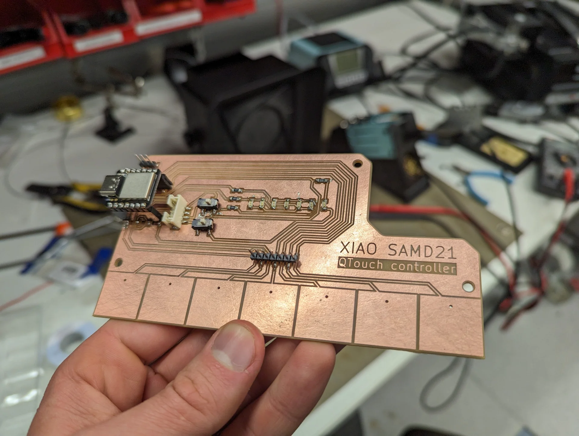
The XIAO SAMD21 QTouch controller board was designed and manufactured during the electronics design week, documentation for which can be found here. It was then programmed to sense changes in capacitance, i.e. touch, through various materials of varying thickness during the input devices week, documentation for which can be found here. It can reliably detect touch through over 4mm of transparent acrylic while still (barely) resolving the capacitance changes through 11mm of paper, i.e. 200 pages of a text book. It was also programmed to distinguish between tap and slide/swipe gestures, which control two state variables power_on and brightness_level respectively, such that the charlieplexed LED corresponding to the pad last touched during the swipe is on if the power is on. Tapping turns the LEDs corresponding to the latest state either on or off depending on its current state.
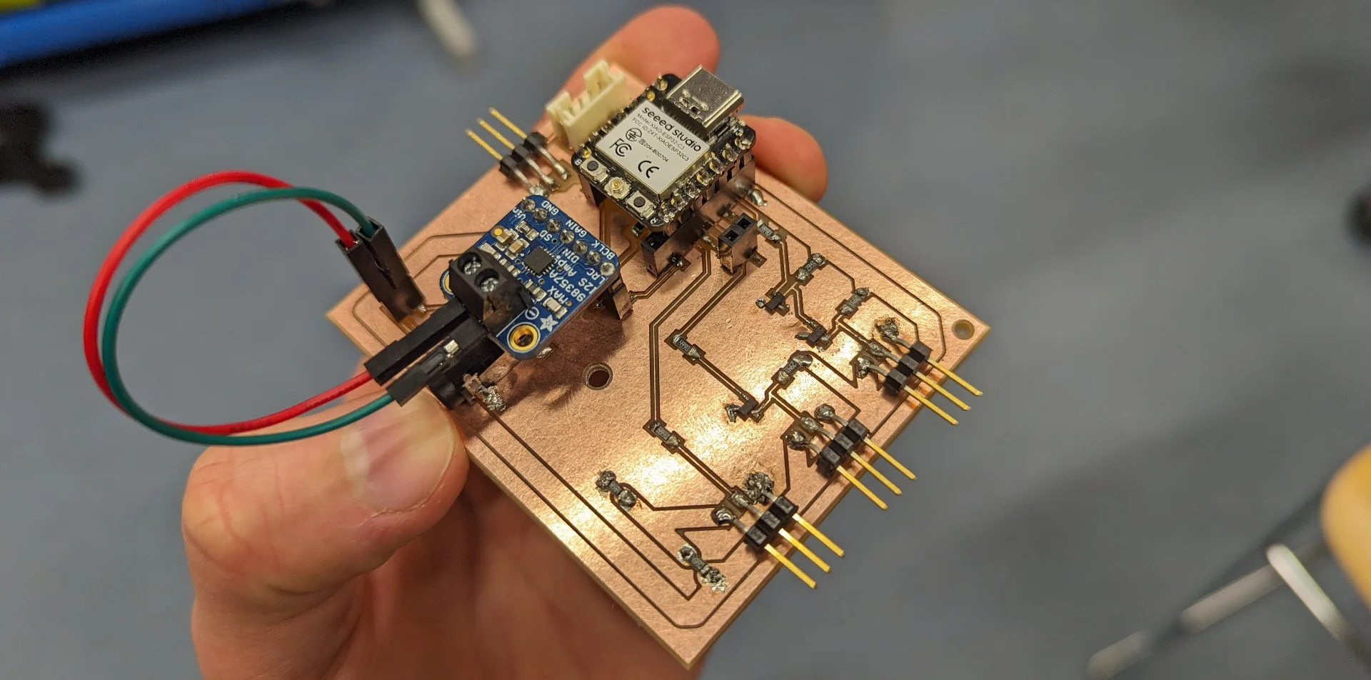
For the XIAO ESP32C3-powered output board above, whose documentation can be found here, I tested four different ways of controlling WS2812B strips but only two of them lit up the LEDs in the first place. Furthermore, none of them displayed the right colors, likely because the strip was not what I thought it was. This issue was indeed solved for the final board by using a newly ordered LED strip with the exact same code.
The output board was really a major failure on its own. I could not make it work with 5V power input directly nor by using MOSFETs to try to step up the logic voltage and we had no level shifters in the lab. The only experiments that did power on the LEDs were directly through 3.3V and by using a voltage divider to reduce the voltage from 5V to around 4.5V so that it was well within the spec but could also be reliably controlled with 3.3V logic. However, this would likely not have endured higher currents necessary for running over a hundred NeoPixels at near full brightness. The board also has audio output but it was miswired such that the 3.5mm jack ground connection and right channel were the wrong way around. However, many important lessons were learned and incorporated to the final board design, which then worked mostly as expected.
Circuit board
Design
The final circuit board is a sort of combination but perhaps even more so a spiritual successor to the input and output boards. It became a roughly 96mm x 64mm board with power delivery, inter-board communication, audio output and four outputs for NeoPixel led strips all on a single board with sockets for the microcontrollers and amplifier for repairability. It can be powered on with any 5V 5.5mm plug and supports up to 9 amps of total current for the LED strips. It also features a switch between the power circuit to the microcontrollers so that they can be powered on with the same power input when the project is ready but could also be programmed independently without having to worry about accidentally frying one’s computer. Below are its schematic and PCB layout.
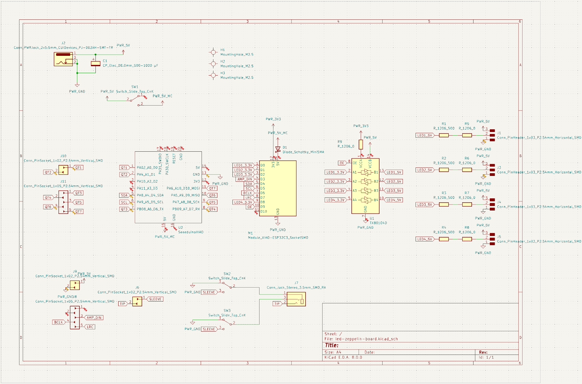
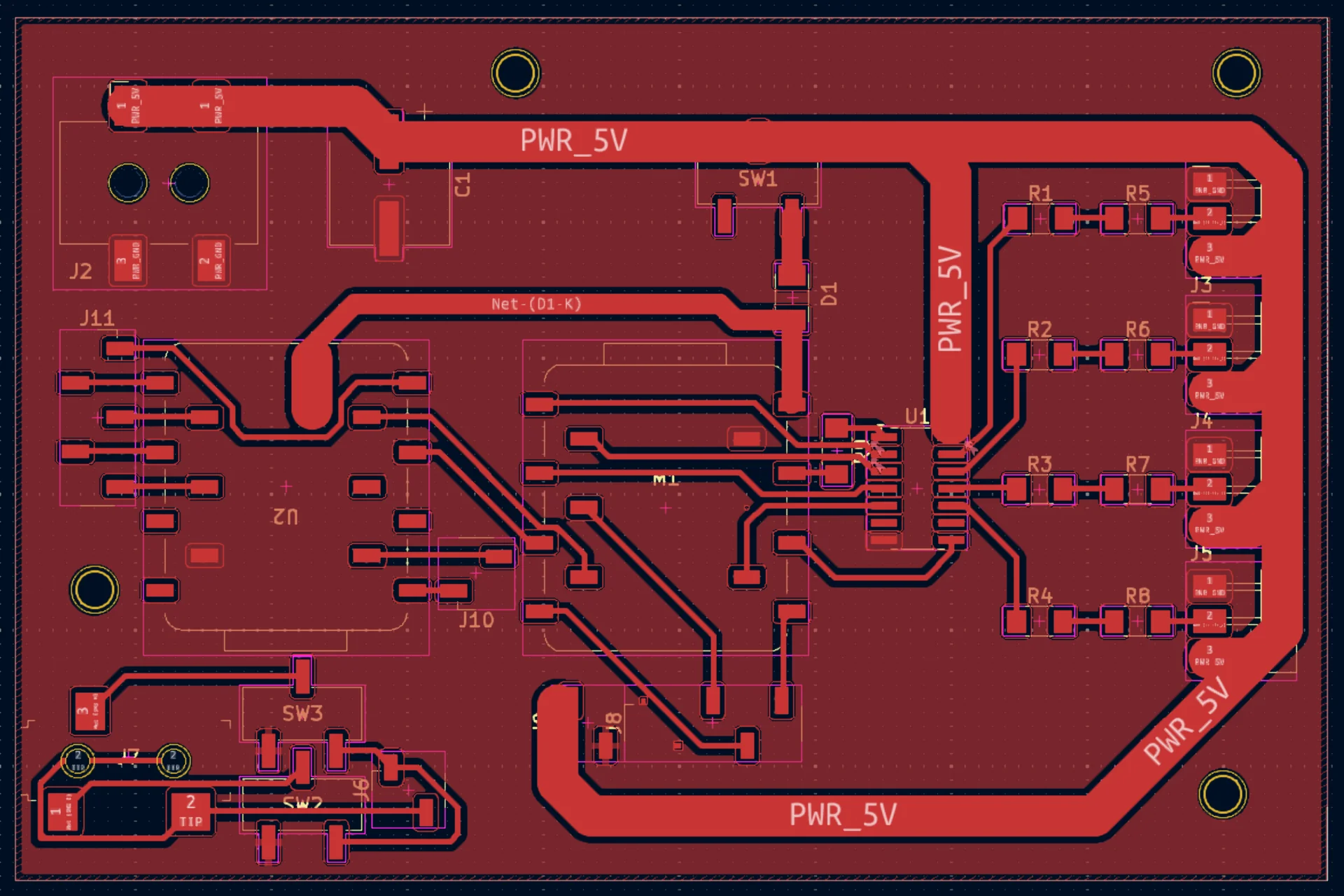
The schematic is roughly divided into four functions. Power delivery in the top left corner, gesture detection in the middle left side, light output in the middle right side and audio output on the bottom, which is identical to the output board, except for the two switches that can be used to switch which of the 3.5mm audio jack pin is ground and which is the other audio channel. The reason for this was that upon further research, it seemed like the original audio output design should have been correct, yet it did not work with my speaker - which I suspected has been miswired as a result. Since it was the only plug-and-play ready speaker I had, I needed to be able to plug it in for testing without losing support for correctly wired speakers.
Most notably, the final board has two XIAO microcontroller boards in similar functions as in the previous boards. The XIAO SAMD21, also known as the Seeeduino XIAO, essentially acts as a 7-channel capacitive touch sensor that also implements gesture detection logic thanks to its QTouch pins, while the XIAO ESP32C3 acts as the main brain of the board handling all heavier logic, output and wireless networking due to its superior 400KB SRAM and 4MB onboard Flash memory and WiFi and Bluetooth 5 connectivity. These are then wired so that they share the power input and ground and are connected SDA to SDA and SCL to SCL to enable I2C communication with the XIAO ESP32C3 as the master, reading changes to the lamp’s state as a result of the gestures processed by the SAMD21.
The majority of the board real estate is used for driving the NeoPixel LED strips, which has been done by attempting to follow all of the best practices detailed in the Adafruit NeoPixel Überguide. These include a 220µF capacitor (highest capacitance in a reasonably sized package available at the lab) connected from the positive terminal to the power supply and the negative terminal connected to ground, a 3mm wide power trace capable of delivering currents up to 9 amps to power on up to 150 fully white NeoPixels at full brightness with 60mA each, 499 Ohm resistors between each XIAO pin and the first NeoPixel of each strip with the distance between all of these minimized while passing through a TXB0104DR 4-Bit Bidirectional Voltage-Level Translator to shift the input voltage level from 3.3V to 5V.
The level shifting had been my most major headache during the output devices week as the NeoPixels powered with 5V could not be controlled with 3.3V logic due to belonging in the CMOS logic family. This means that for a bit to be registered as a “1”, it must be above 5 * 0.7 = 3.5, which is just above 3.3V. Our lab had no logic level shifters, my attempts at using MOSFETs instead did not work and using a voltage divider would have run the risk of breaking under higher currents, whereas powering on the LEDs with 3.3V would have resulted in running them out of spec. In response to my struggles, our instructor and the Aalto FabLab Master Krisjanis Rijnieks ordered some of the TXB0104DR level shifters, which immediately solved ALL of my problems. The lesson is: if you do not have any, buy some. It is really that much easier.
Integrating them to the board was also delightfully simple and straightforward. According to its datasheet, the smaller voltage between 1.2V and 3.6V should be connected to port A and the larger voltage between 1.65V to 5.5V should be connected to port B. According to my reading, the OE pin controlling the output impedances is optional, whereas ground is obviously mandatory. This leaves eight pins, with four of them on each side corresponding to the “4-Bit” component of the name. The ones on the A side input and output signals with the same voltage as is connected to port A and the ones on the B side do the same but with the higher B voltage. Hence, the 3.3V output of the XIAO is connected to port A along with the XIAO output pins on the same side and the 5V input power trace is connected to port B with the LED input pins on the same side. OE is connected to an otherwise unused XIAO pin and 0 Ohm resistors are used to jump over some traces or alternatively, the shared ground in order to match its thickness more closely with the input power trace.
In my output board, there was a thick trace for the power too in order to be able to tolerate high currents but ground was mostly ignored in terms of trying to match them. It was connected but much thinner, which Kris pointed out might cause problems. Hence, this time I paid attention to the thickness of the overall ground layer as well, adding some 0 Ohm resistors to increase its area especially near the LEDs. Additionally, a 220µF capacitor was added between the positive and negative terminals of the power jack to even out potential spikes.
A switch controls whether or not the microcontrollers are powered from the same source and a Schottky diode after it ensures that current only flows towards the microcontrollers, which also enables the usage of the 5V pin of the XIAO ESP32C3 as a voltage input as explained here. The same capability was not explicitly listed for the XIAO SAMD21 and hence I just drew a large power trace beneath its VIN pin on the bottom, which was utilized in a bit of an unorthodox manner as shown below.
Assembly
I tried to mill the board in what had already become routine fashion but was stopped in my tracks by CopperCAM not importing the gerber files properly. Instead of rectangles with a margin, it interpreted the level shifter footprint (imported from the general KiCad library instead of the fab library used for all other parts) as having connected circular pads, which obviously would not do, even though KiCad’s gerber previewer opened them just fine. As CopperCAM is so poorly documented with few issues anywhere on the entire internet, I quit very soon and opted to just ask Kris the next Monday, who pointed out that the footprint had rounded rectangle pads instead of regular rectangles, which caused the issue. Changing them to rectangles solved it.
Otherwise, the milling went mostly well, except for the fact that the 0.8mm drilling tool had not drilled quite uniformly, so that board was more severely stuck to the stock than usual and all holes had not gone entirely through. This might also have something to do by me having accidentally picked the double sided material. It required significantly more force but I managed to carefully loosen it and I poked the holes through with a thin screwdriver, leaving me with a PCB that was not quite as crisp on the bottom but still looked great as any on the top.
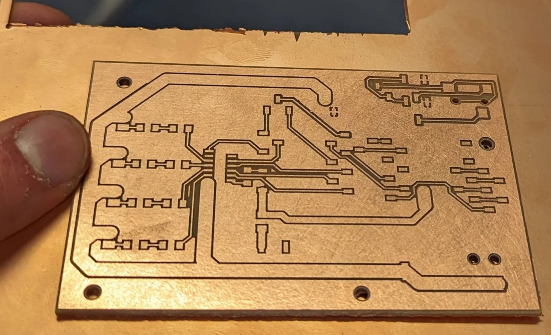
Comparing the above picture to the PCB layout, it can be observed that they do not quite match perfectly. This is because I changed the KiCad PCB layout depicted further above to what I originally intended it to be. In the board that I produced, the power and ground to the amplifier (close to the top in the above image) are the wrong way around, which I only realized much later.
It was also an effort to figure out which way around some of the components go, such as the capacitor, particularly when I could not find the specific capacitor model anywhere on the internet. Instead, I found this datasheet for Panasonic capacitors, which indicated the dark streak on the wider side of the base to be the negative polarity marking. I then made the risky assumption of the markings being at least semi-standardized and soldered it accordingly, which worked delightfully.
This, however, was the simplest orientation to figure out. The small Schottky diode ensuring one-way power delivery to the microcontrollers had such small, dark markings that it took a long while of angling it below some light to find any asymmetries whatsoever that would indicate its polarity. Eventually, I discovered that one end seemed to have slight line that seemed to be carved. With a quick Google search I found this page which listed how polarity is indicated in most common surface mounted devices (SMD). For components with two pins, the strip or a coloring seems to usually indicate the negative electrode for polarized capacitors, LEDs and diodes.
This is not quite as straightforward for SMDs (or SMT - Surface-Mount Technology) with more than two pins. Generally pin 1 is indicated by a dot next to it but the TXB0104DR level shifter had none in sight. Instead, it had a thick line from the left to the right side as well. According to the datasheet it comes in 6 different packages, 3 of which seemed to have the indicator pin but the rest did not. The ones at our lab belonged to the latter category with 7 pins on two sides in a “D or PW Package, 14-Pin SOIC or TSSOP”. I was quite clueless about this letter soup and with my (de)soldering skills there would be no second attempt on this board.
After scrolling the Texas Instruments package page for a while with the help of CTRL + F, I found this document, which seemed to match my footprint closely enough. A few other similar ones seemed to have the same design rules with the line stretching from the first pin to the last with an ever so slightly more prononunced fillet on the pin 1 side. I decided this was as far as I would likely get, soldered it on and thankfully found it to be working! The second to lowest pins on both sides were entirely disconnected and merely a part of the specific package.
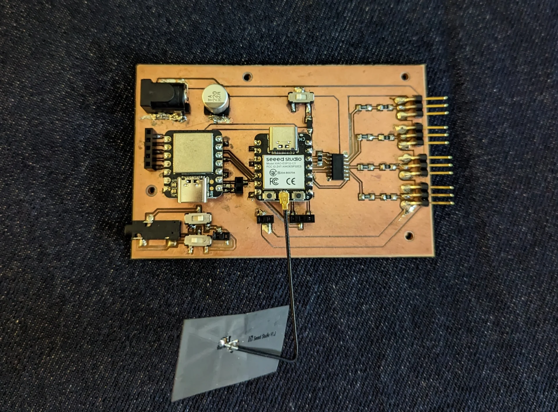
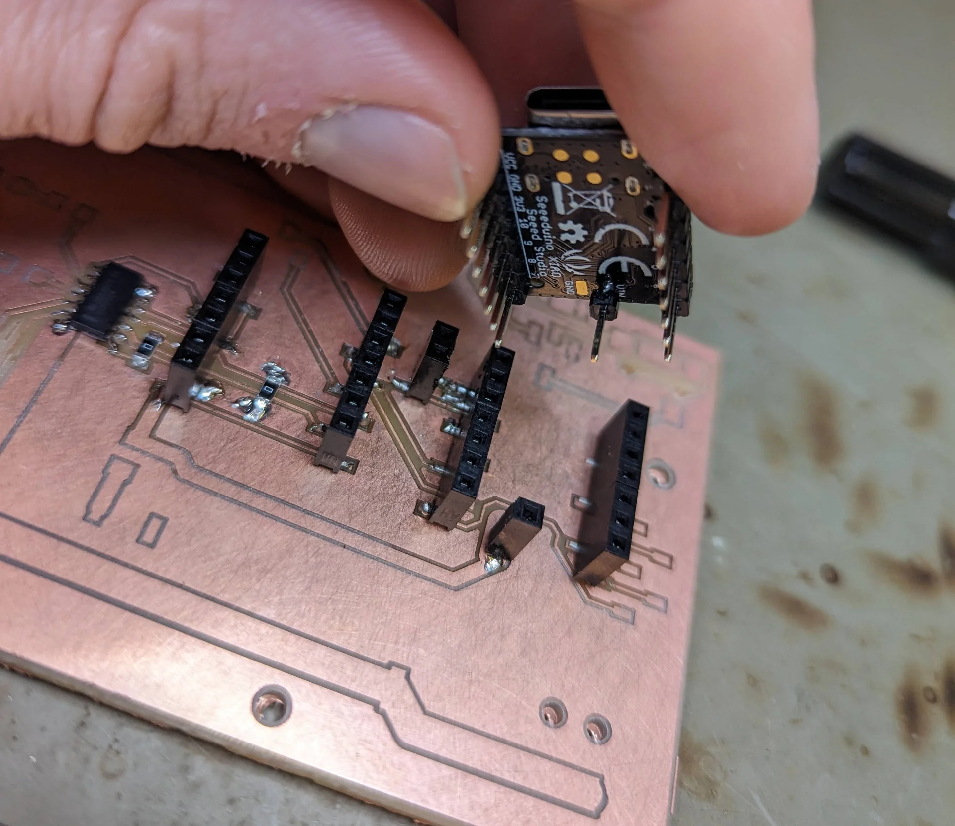
The bit of an unorthodox power delivery mechanism to the XIAO SAMD21 alluded to earlier in the design phase involved a bit of a riskier solder joint that is likely not quite as durable as many others but works just as well, provided it is not stressed too much at least. As can be seen in the below image, I soldered on a single male header to the XIAO’s VIN pin perpendicularly to the rest of the board, which connects to a single female header soldered on the wider power trace on the board. This was done by first soldering the male header to the board whilst connected to the female header and then soldering the solitary female header to the board after soldering the corners of the longer headers. The result is perfectly stable and functional although I would avoid excessive stress to it.
Upon testing it, the LEDs worked perfectly as did the mechanism of powering on the board and microcontrollers from both the same as well as two different sources. However, when trying to mount on the MAX98357A Adafruit I2S 3W Class D Amplifier Breakout board, I noticed that I had accidentally connected the power and ground to its socket the wrong way. I did not have one near me when designing and KiCad obviously does not care about the orientation of components as long as they are wired correctly on a pin-to-pin level.
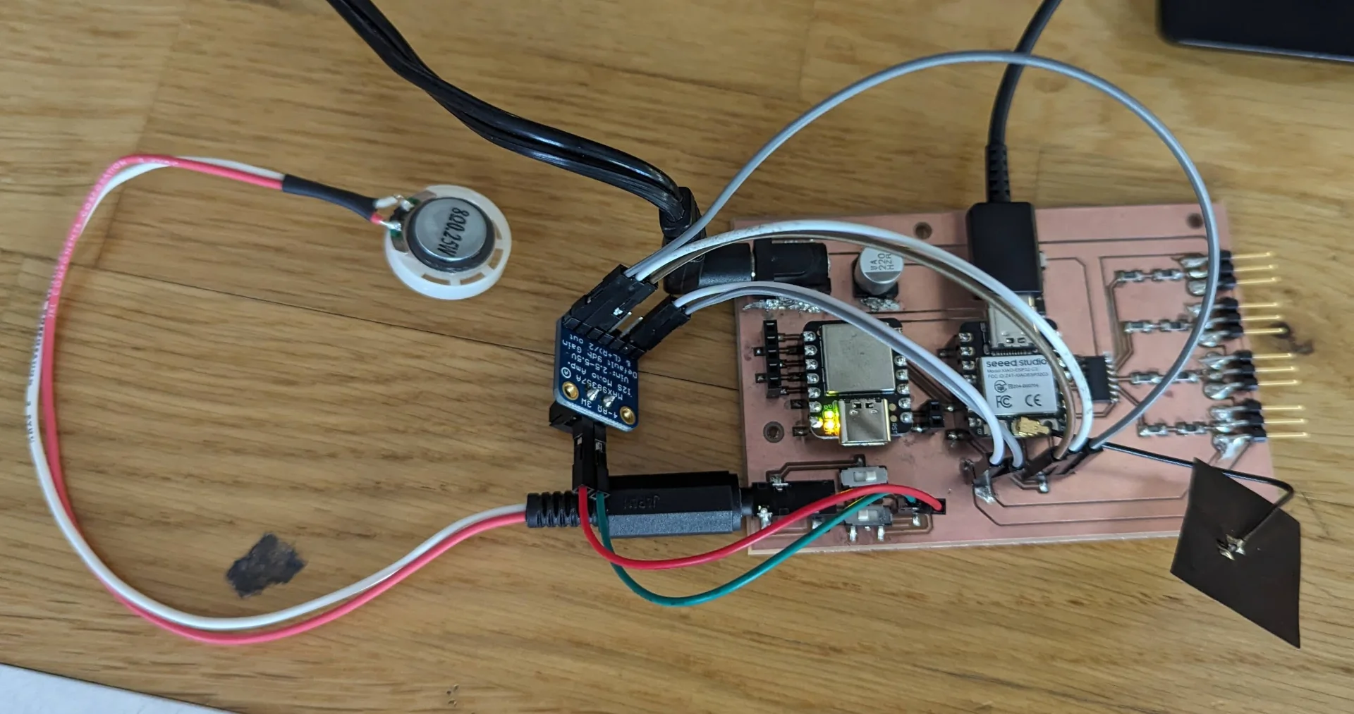
This was incredibly unfortunate and I went to correct the mistake immediately in the board design, hence the difference between the layout diagram and the actual board. To get quickly around it, at least for testing purposes, I simply connected the amplifier with wires but even then it did not work. After a bit of poking with a multimeter’s continuity checker, I noticed that the BCLK pin’s solder was touching ground, the removal of which caused faint noise from speaker when plugged in and running the output week’s speaker test code. The faintness of the sound was likely due to the very weak speaker and not the amplifier. It could also be made slightly louder by increasing the amplitude in the code but this was barely noticeable on the speaker. With wired earbuds, the difference was much more audible. The setup is unfortunately a bit ugly with all the extra wires as can be seen below but these could be made shorter and hidden inside the lamp if necessary.
Kris recommended potentially using Nail polish on the thick power traces to make them safer.
The headers with two sockets are unfortunately very fragile and I managed to accidentally rip both of them off along with their traces while assembling the lamp. Hence, the speaker connection ultimately remained unused and it did not matter that the wiring was a bit off.
Kris bought some 5V 7A power supplies as well and gave me one of those, solving the power delivery questions. The power budget is calculated in System Integration. I set software headrooms ranging from 2% to 8% for additional safety although with 110 LEDs and no sound output, I could drive them at almost maximum brightness relatively comfortably.
Diffuser & stand
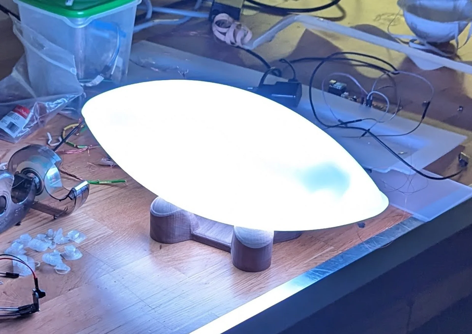
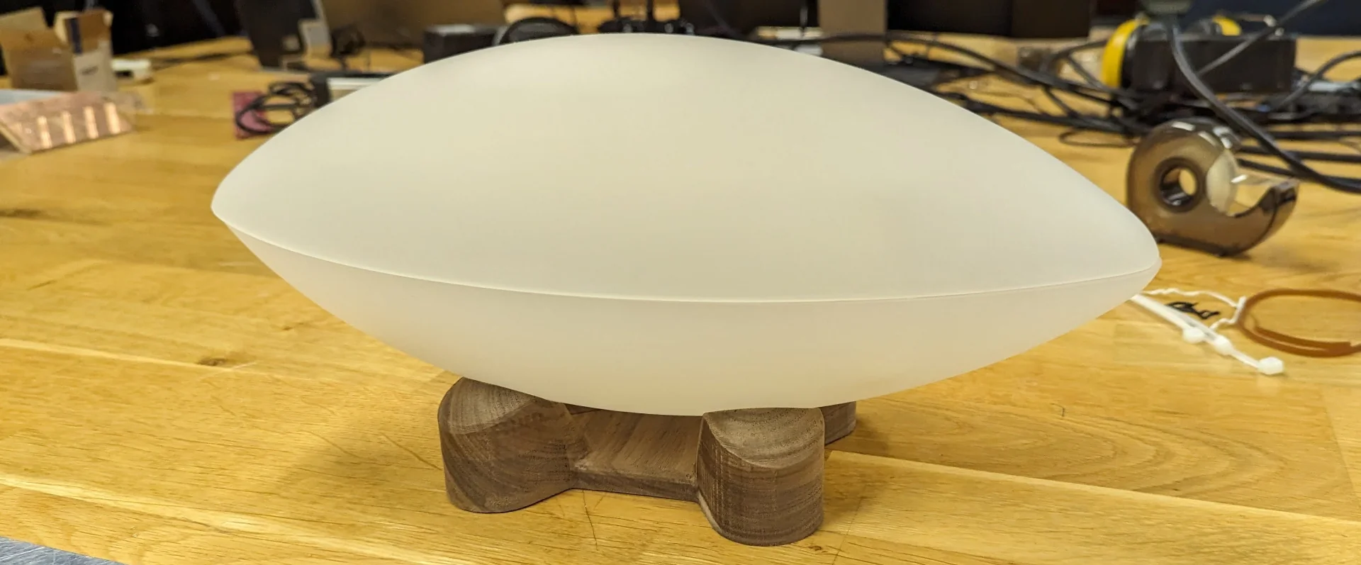
The lamp was redesigned from the render to a manufacturable form, which is documented in System Integration. The diffuser was created during the wildcard week via 3-axis milling SikaBlock, over which 3mm translucent acrylic was vacuum formed and then sanded for an entire night. The stand was also 3-axis milled from a block of hard wood. These are extensively documented in 3-Axis Milling & Vacuum Forming.
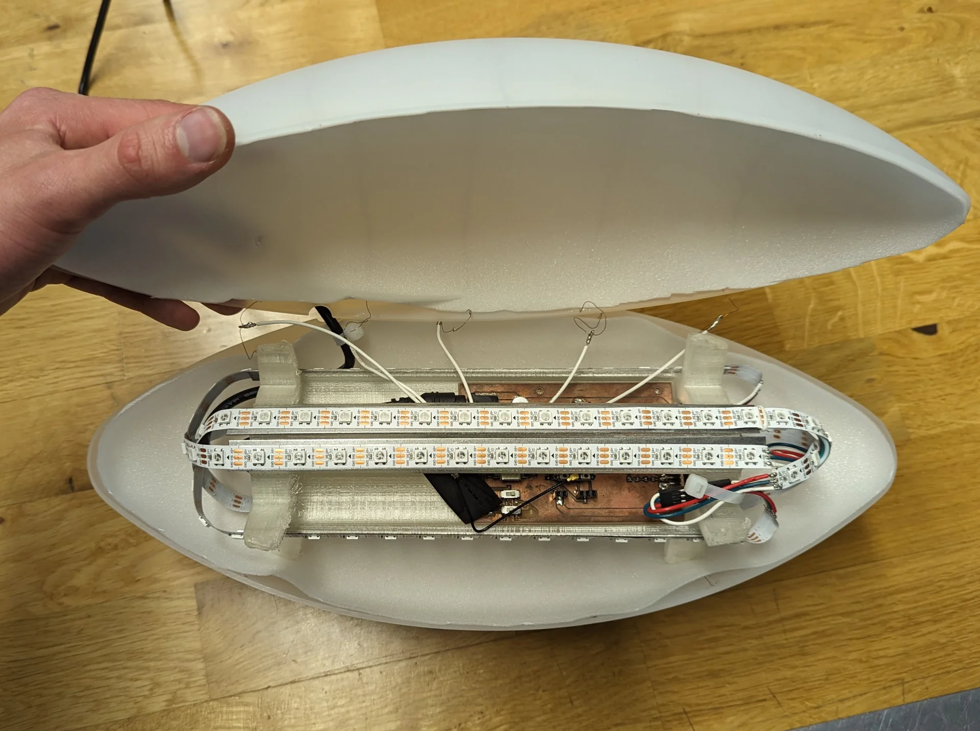
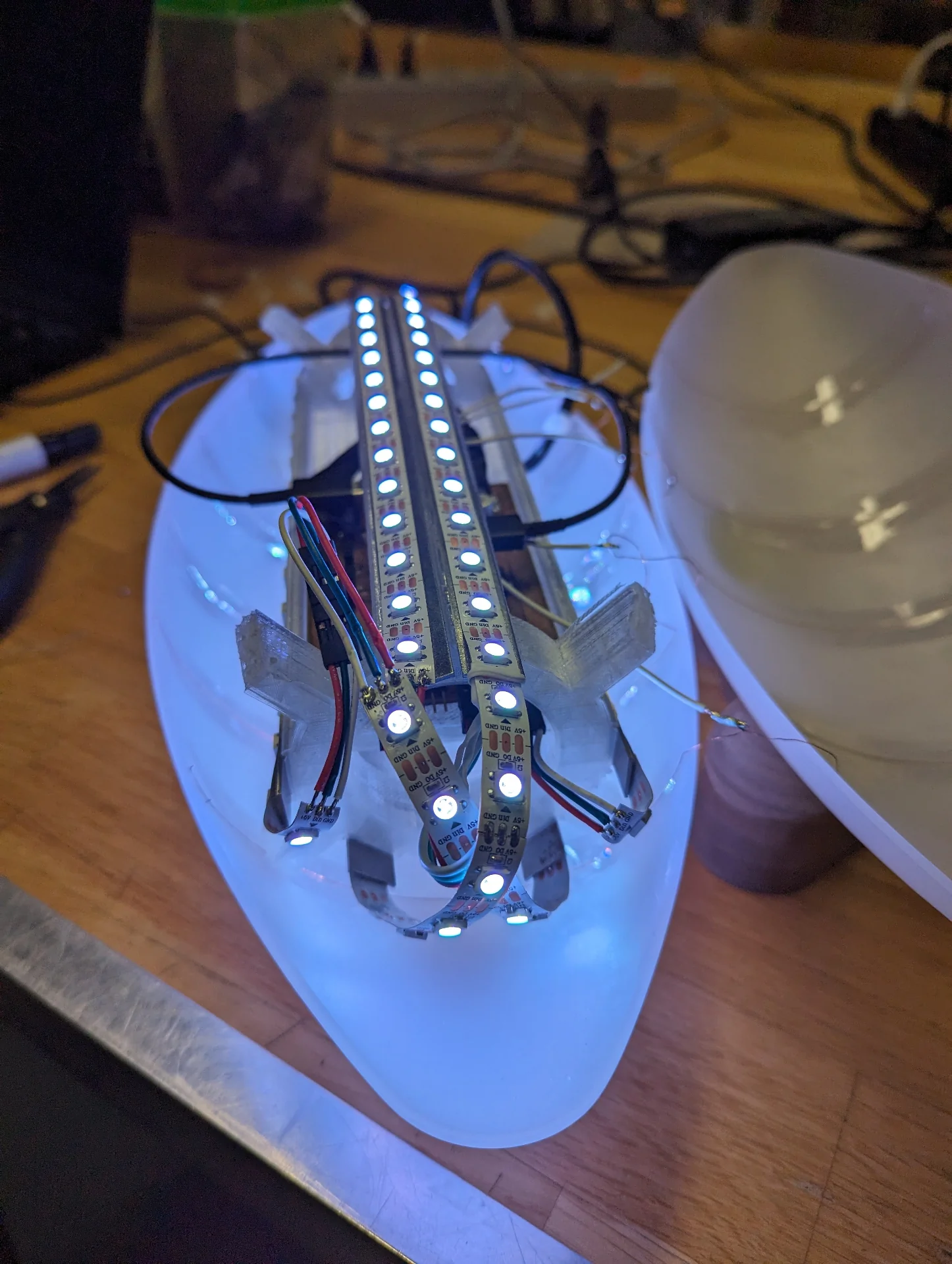
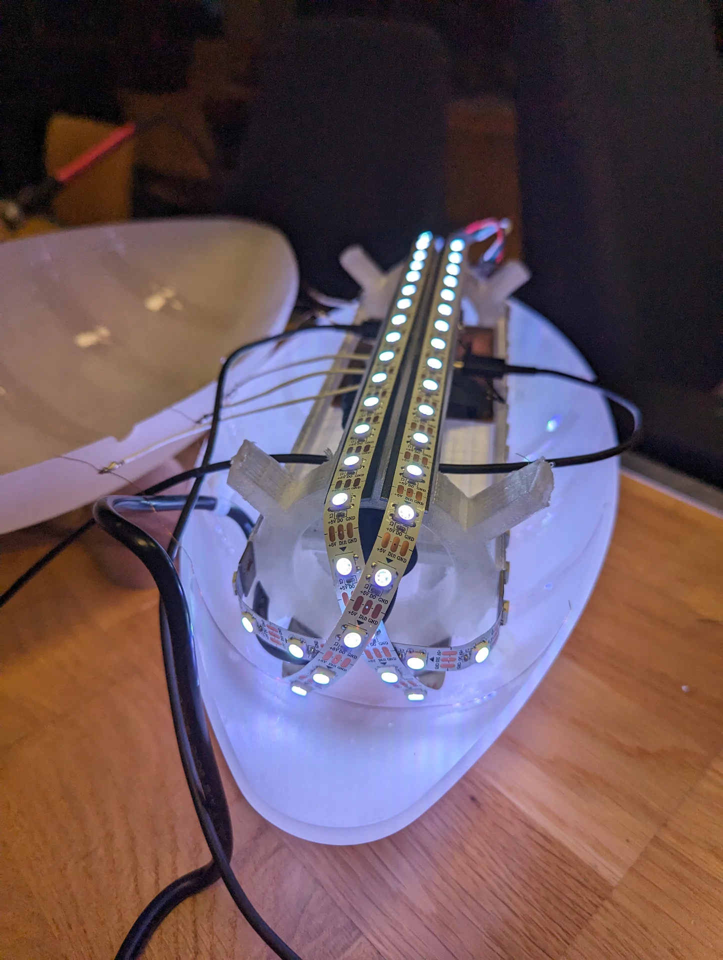
System integration
An internal structure was iteratively designed and 3D-printed in System Integration to hold the PCB and LEDs in a maximally diffusing arrangement inside. The lamp was assembled by placing the PCB on the internal structure, connecting custom cables to the XIAO SAMD21’s QTouch pins that had exposed dual copper wires taped on the inside of the diffuser for sensing capacitance changes, gluing the LED strips on the cut metal heat sinks glued to the internal structure and coating the inside with 2mm thick vacuum formed LED diffuser foam, all of which is documented in detail in System Integration.
Programming
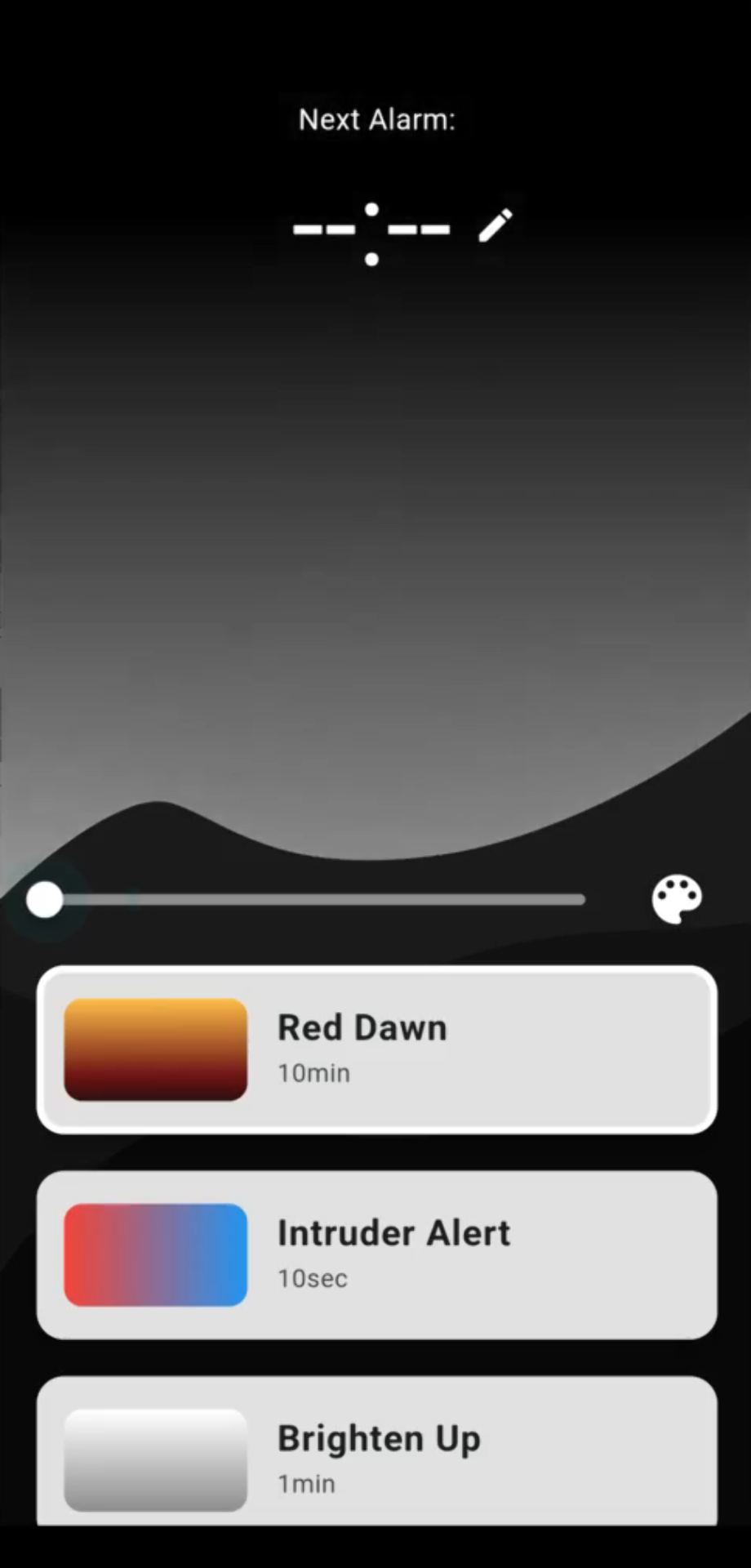
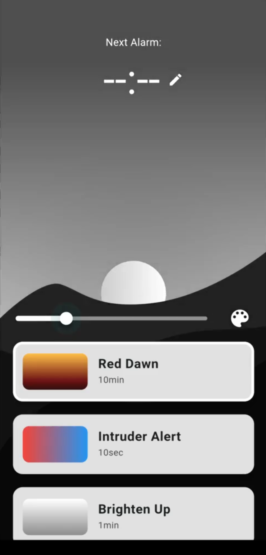
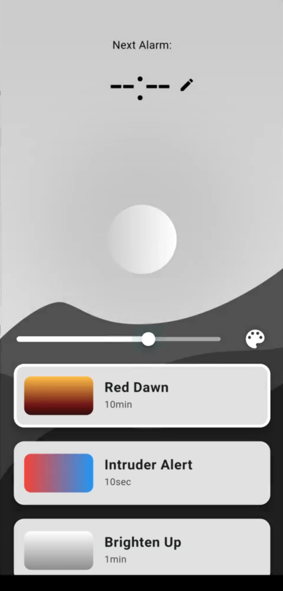
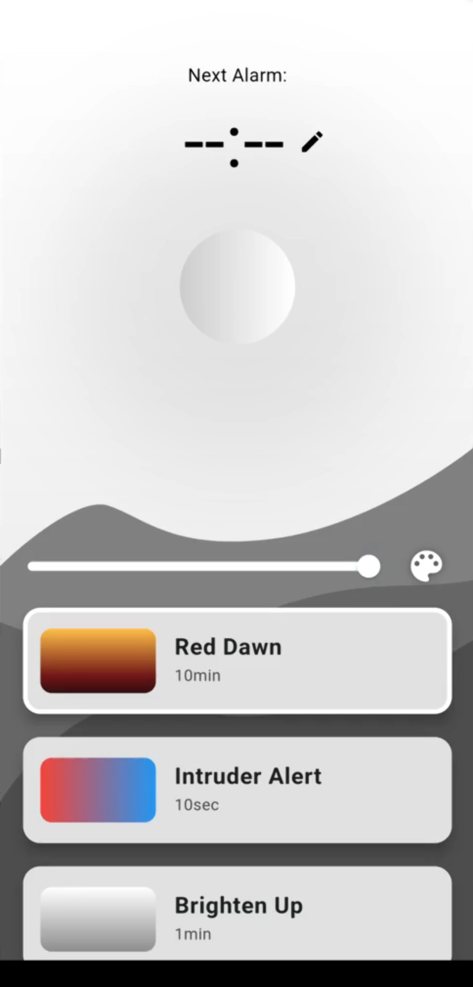
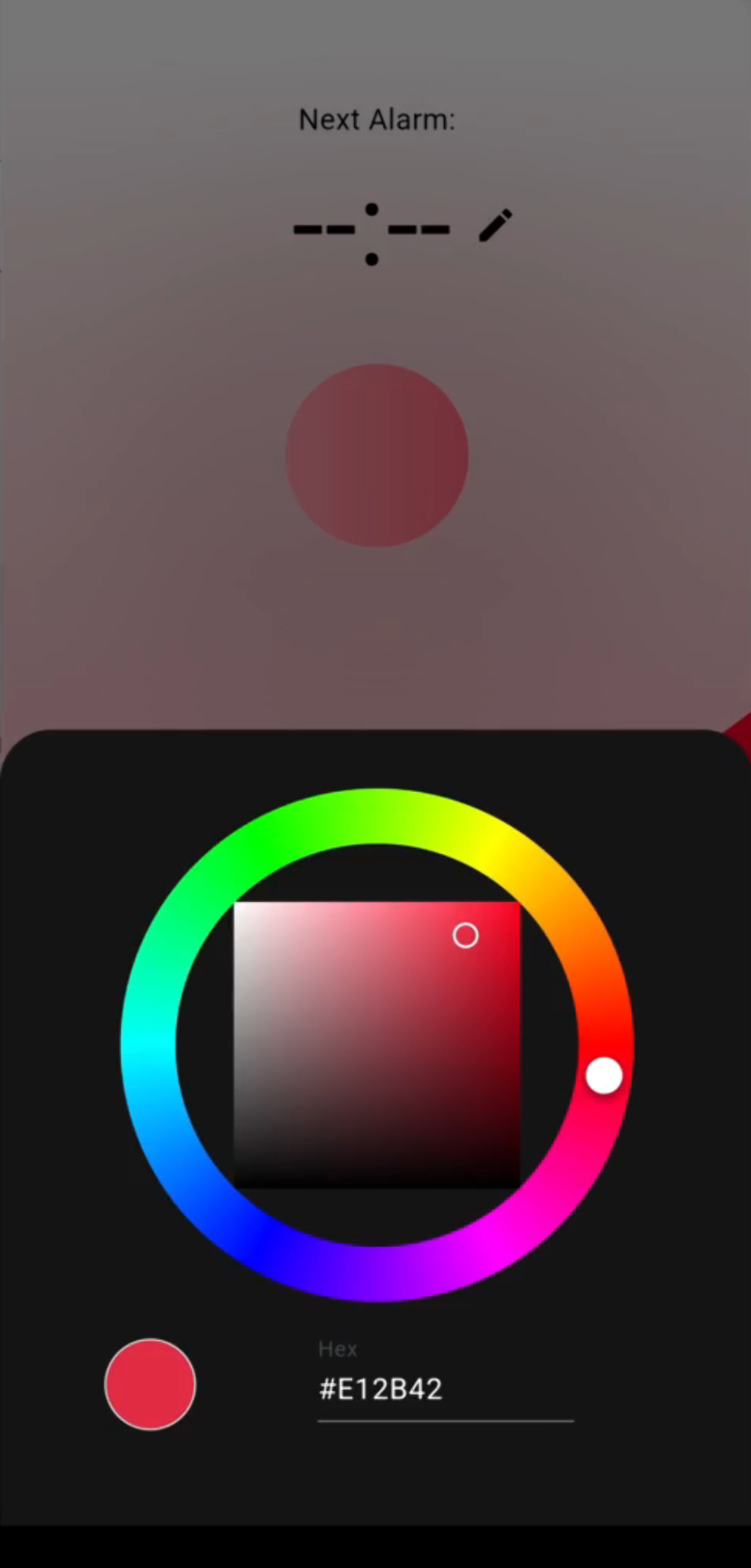
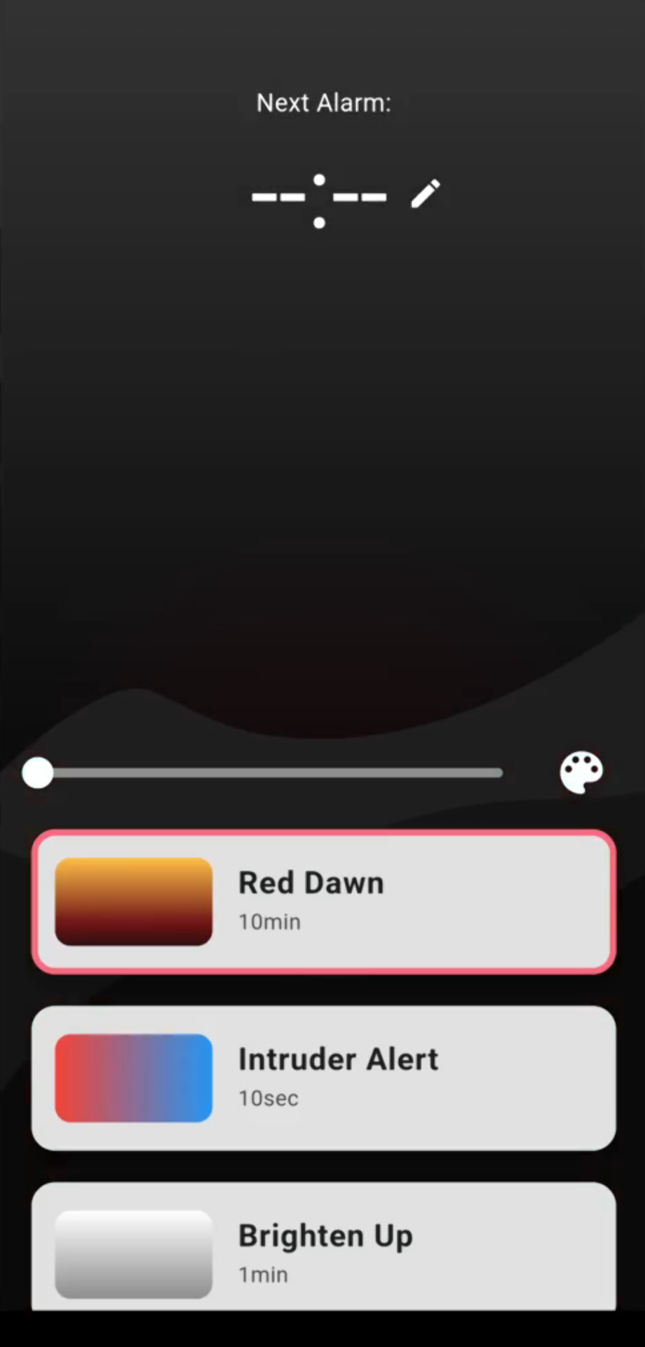
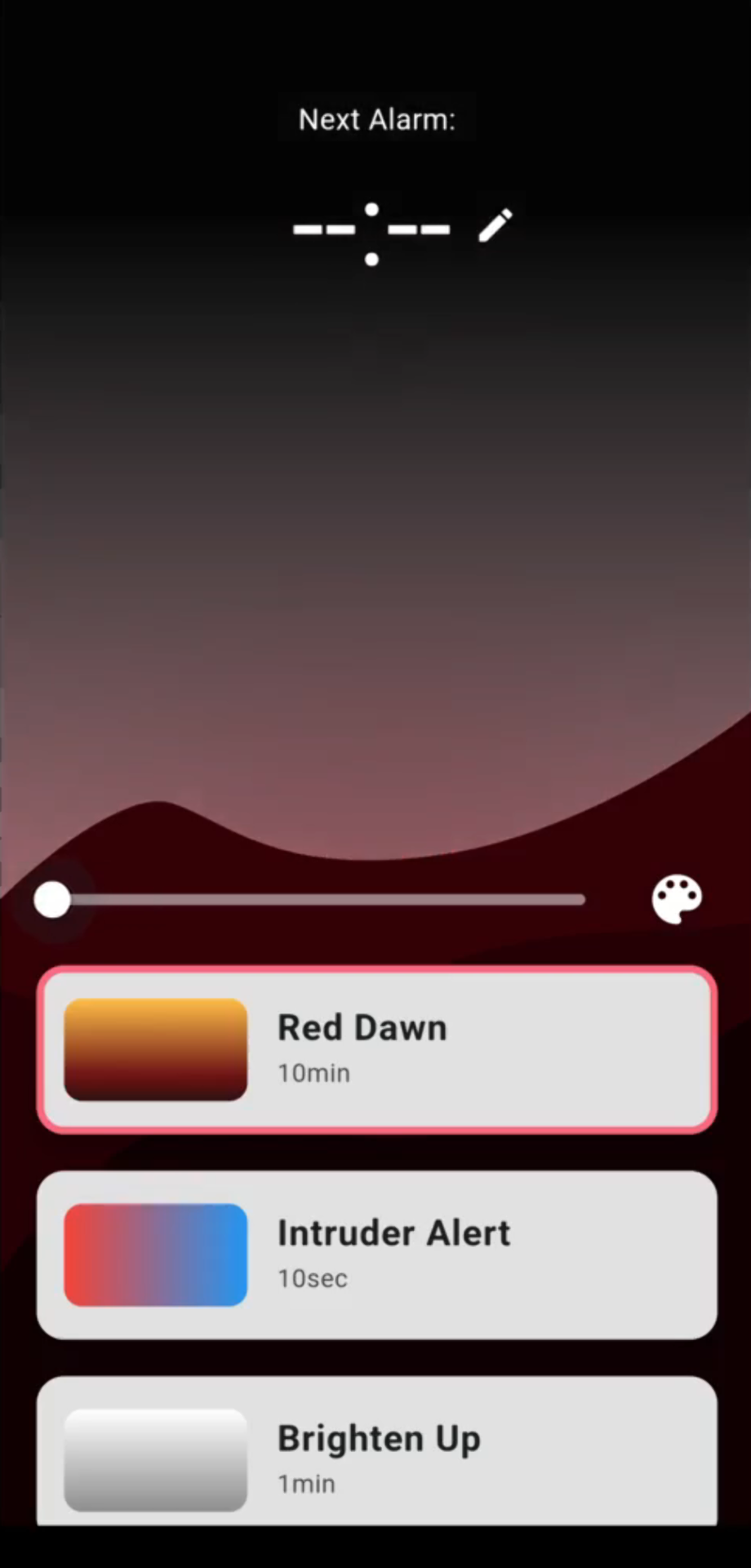
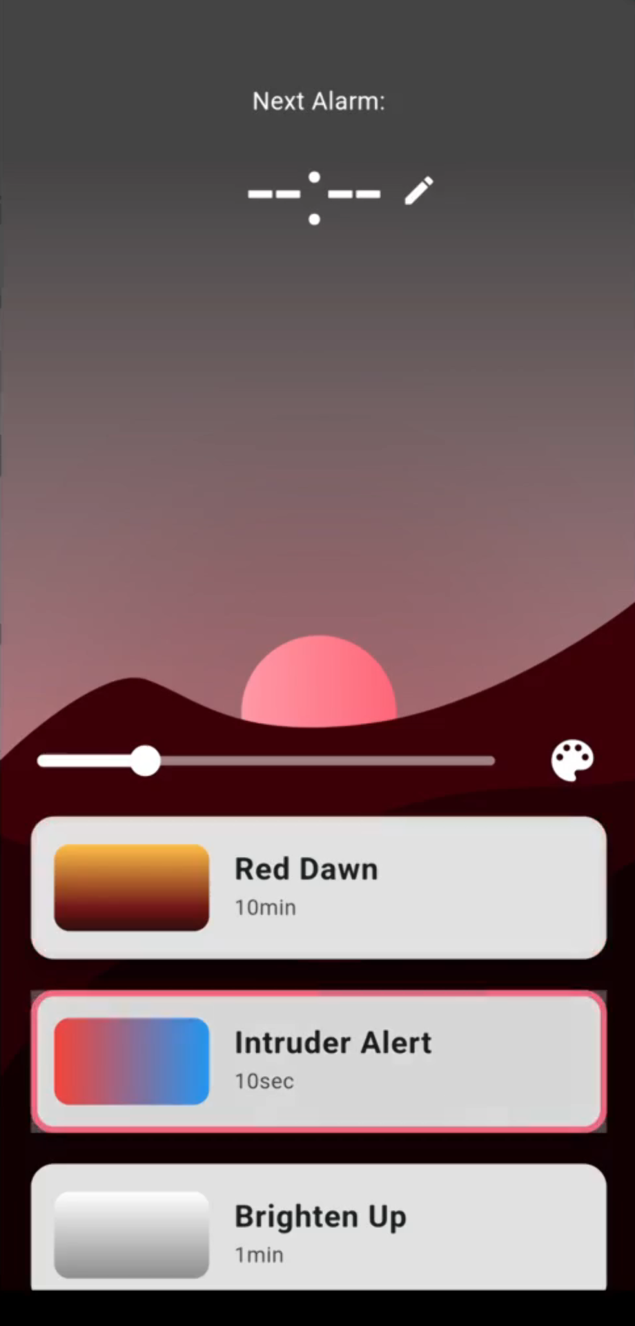
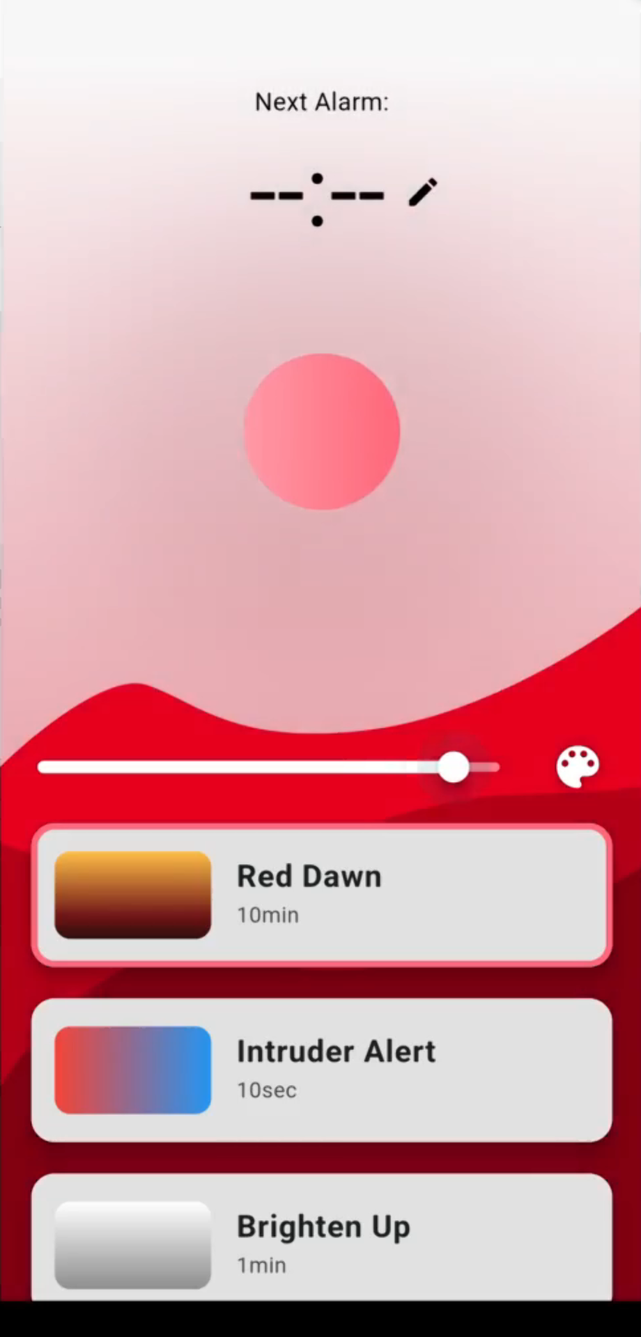
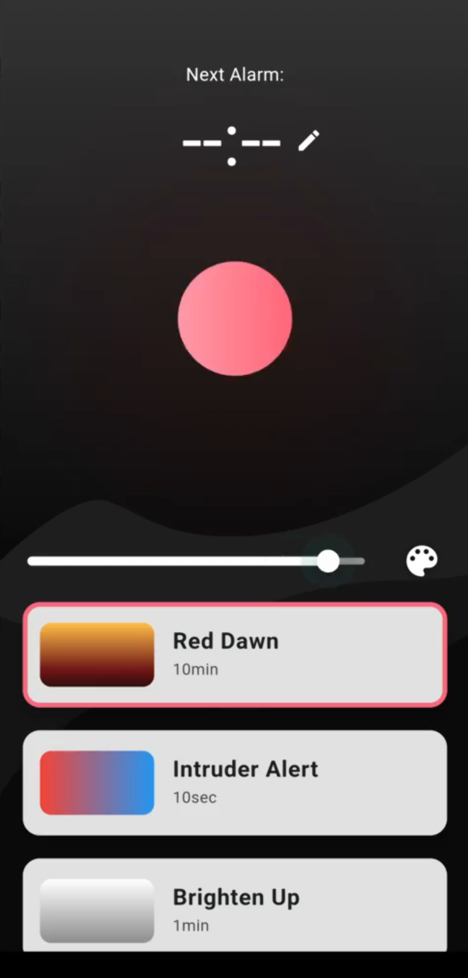
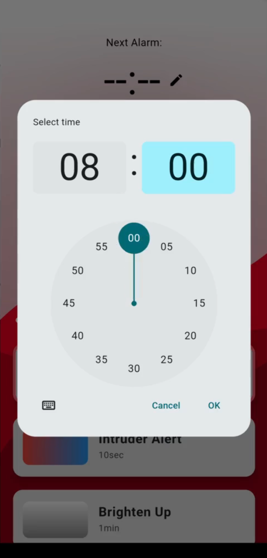
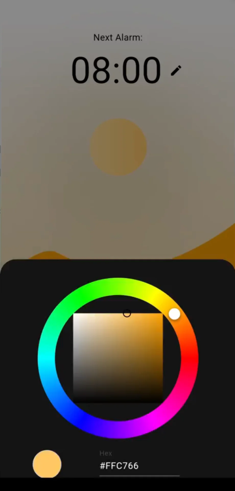
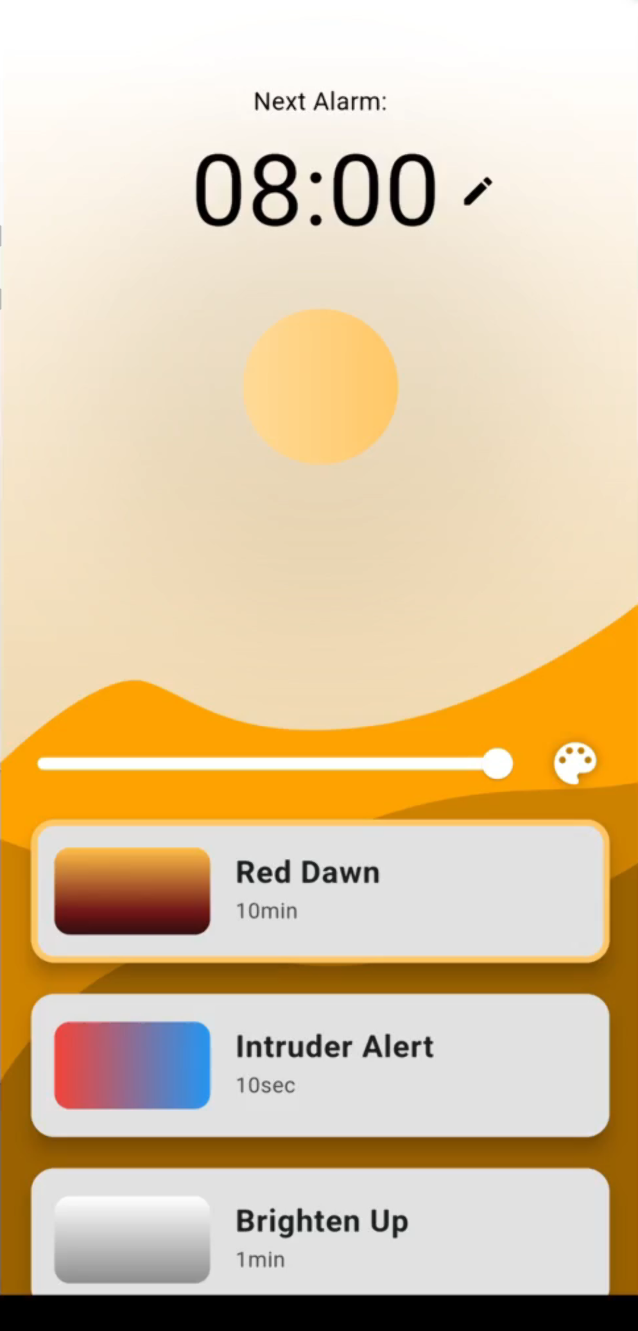
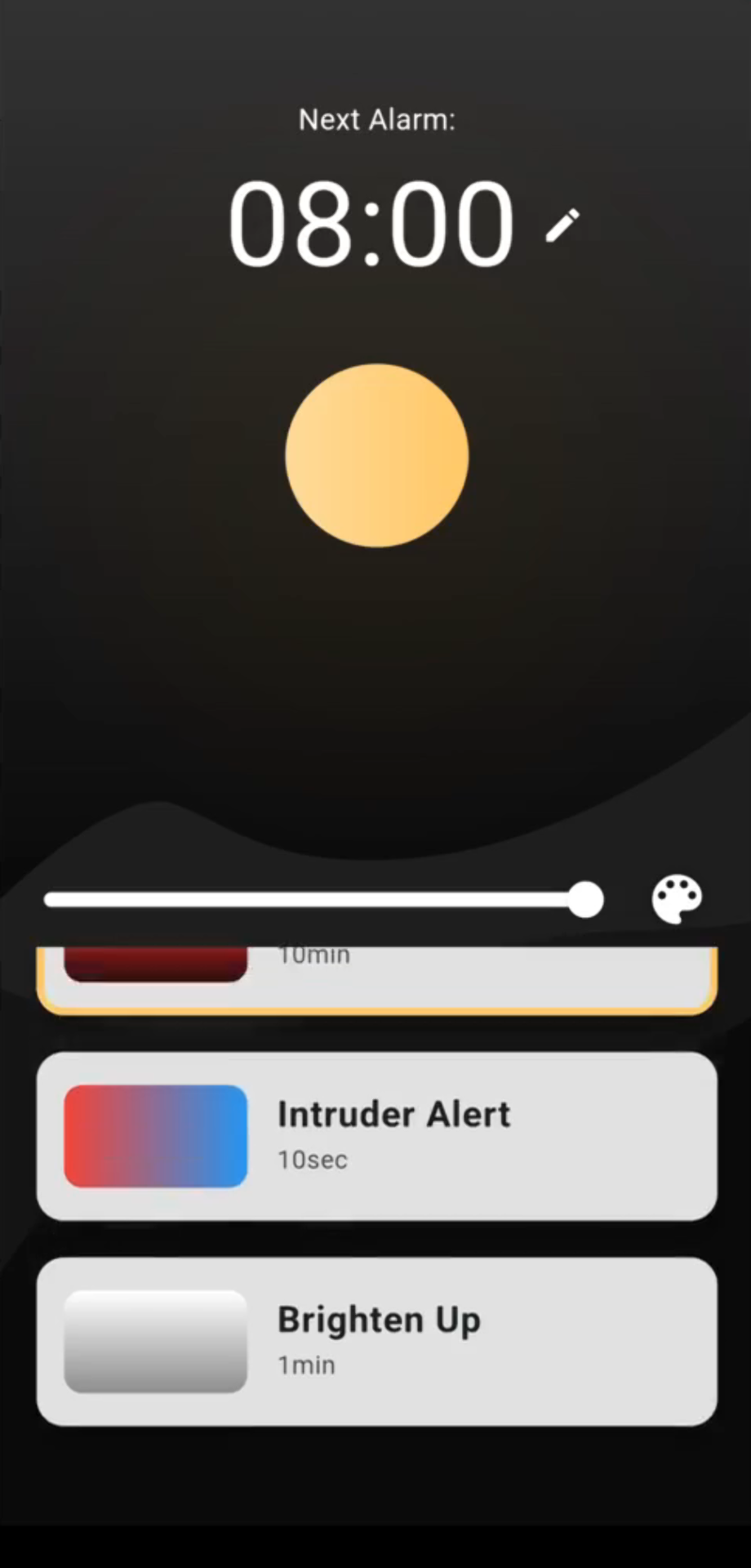
The XIAO SAMD21 gesture detection code originally written and documented in Input Devices was fine tuned for the assembled lamp and made to communicate with the XIAO ESP32C3 code responsible for controlling the LED strips and communicating over Bluetooth Low Energy (BLE) with the Flutter mobile app, via I2C. The I2C and BLE communication are documented in Networking and Communications and the design and development of the Flutter mobile app is documented in Interface and Application Programming. It can be used to control the on/off state and brightness of the lamp, as well as change its color and set alarms with predefined animations in a dynamic user interface (UI) that responds to the selected color and brightness with changes to its background landscape.
License
I decided to license the final project and this website, its contents and the repository it lies in with the Creative Commons Attribution-NonCommercial 4.0 International Public License or CC BY-NC 4.0 for short, as it is very permissive, allowing people to productively use the documentation and even replicate projects for personal use, but prevents commercial use to which I would very much like to be a party to, should someone find some of the projects that good. Do not hesitate to contact me via any of the links in the left sidebar if you are interested in using some of the projects commercially. Most likely I will be enthusiastic to get involved.
I found the license from the excellent creative commons license chooser, which allows you to configure the basic properties as you wish and spits out a license notice, such as “Miro’s Digital Fabrication Portfolio © 2024 by Miro Keimiöniemi is licensed under CC BY-NC 4.0” in this case.
I compared it to a few of the most popular open source licenses: Apache License 2.0, MIT License and GNU General Public License (GPL). The Apache License 2.0 and the MIT License are very permissive licenses allowing essentially free usage, modification and distribution of code with varying attribution requirements, whereas GPL is a copyleft license, which requires all derivative works to use the same license, which most notably requires publication of the source code and ensures that all derivitave works are similarly freely usable, modifiable and distributable.
Creative Commons licenses are typically not recommended for software but the majority of content in this repository is actually not software but text, images, videos, 3D-models and other design and manufacturing files and hence the CC BY-NC 4.0 license felt the most appropriate as I only wanted to have one license for the entire repository and, as even with software, it still communicates the right intention and idea, that being free non-commercial use, even if it were not typically directly applicable in that particular domain.
Reflections
I have always evaluated the project by its user experience, utility, novelty, overall level of completeness, seamlessness of system integration and potential commercial viability. Although not quite having all the initially planned features, let alone any of the potential extensions, the final results scores pretty high on all of the metrics for me.
The user experience of controlling the gesture controlled lamp via touch is great, although seemingly slightly dependent on the conductivity of the user, where for some it flickers a bit more, whereas for me it is tuned not to do so practically at all. This results from the relatively crude gesture detection code, which could still be polished further by, for example, more sophisticated averaging of the readings. Regardless, it is very responsive usually behaves exactly as expected. Controlling the lamp via the mobile app is also very seamless with the app connecting to the lamp very quickly and the brightness and color values transferring with a slight delay but as a smooth, continuous animation.
The utility of the lamp is not quite as great as originally envisioned, due to the alarms not being completely implemented. This should be a relatively straigthforward and quick extension, however. Regardless, it is quite decent as a bit of a design element and as a lamp with adjustable brightness, which in itself is still too rare. Moreover, the interface for doing so is very intuitive and easily reachable at all times with the only criteria being that the lamp must be at arm’s length. In fact, it did not even occur to me in the design phase, but a professor visiting the Fablab pointed out that it is actually great for accessibility too due to the intuitiveness and how error tolerant it is for someone with, for example, very shaky hands. Additionally, color control is great for, for example, reducing the amount of blue light viewed at night.
I am not sure about the novelty dimension as I have not really researched it too much apart from sunrise alarm clocks, of which it is considerably different. I have not bumped into any at any stores ever either, so such things are not at least widely spread yet, making it novel enough to be interesting to me. Certainly, the hypothetical final version with all the extensions would be highly unique as it could be characterized to function similarly to an Amazon Alexa but with light and the even Pixar-like character qualities that come from it. Hence, with additional development and cutting down the costs, I believe that it could eventually be very commercially viable.
In fact, I might one day return to it with a future co-founder after some successes in software first, which are much easier to attain due to the often close to neglible fixed costs. I am not quite so committed yet as to take a loan for further development and mass manufacturing but if I were to come up with some extra capital, I might be very interested in taking it all the way to what I originally envisioned. In the mean time, however, it will likely become my nightlamp and potentially alarm clock as well if I get the time to implement that functionality.
The overall completeness is also a bit reduced due to omitting the sound output, but this is not actually noticeable to the end user and as all the other parts work mostly seamlessly together to create a coherent user experience, it can be said to be complete. The system integration is, as discussed somewhere above, partly deliberately perhaps the most lacking domain due to the shadows cast by the conductive wires and the diffuser halves not fastened together. These result from the lack of resources and wanting to leave some room for further improvement respectively though, and hence I think it is okay for the prototype.
Overall, I am very proud of the very usable proof-of-concept prototype and see myself actually using it in my day-to-day life, which is a major win. This was an incredibly intense course, particularly with all the extracurriculars of taking four additional courses and joining the Miitti App startup on the side, but ultimately definitely worth it being able to walk away with a somewhat impressive portfolio and long-needed custom solutions and decorations for our apartment. Reflections on those and each separate part of the process can be found in their respective documentations.